
Resistance Welding Equipment Selection: Comparing Machines, Controls, and Industrial Applications
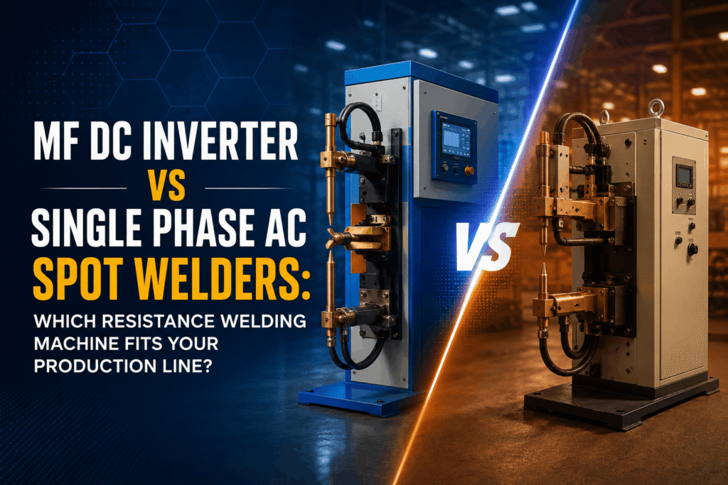
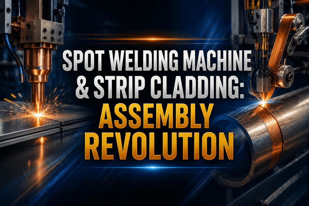
Resistance Welding Equipment Selection: Comparing Machines, Controls, and Industrial Applications Selecting the right resistance welding equipment is one of the most vital capital investments an industrial plant manager or process engineer can make. Modern manufacturing floors—spanning automotive assembly lines, sheet metal fabrication facilities, electrical component manufacturing, and heavy appliance production—demand structural integrity, rapid cycle times, and minimal thermal distortion. Because resistance welding relies on internal heat generated by material electrical resistance rather than external arc flames or costly shielding gases, choosing appropriate resistance welders directly governs your unit economics, energy efficiency, and operational uptime. However, navigating the technical landscape of modern resistance welding machine choices requires evaluating much more than transformer ratings or mechanical footprint. Fabricators must evaluate power delivery architectures, such as Single-Phase AC versus Medium Frequency Direct Current (MFDC), specialized machine frames like spot, projection, and seam systems, sophisticated welding controller feedback mechanisms, and integrated automated clamping systems. This comprehensive guide provides an engineering-grade comparison of machines, digital controls, and real-world industrial applications to ensure your factory selects the optimal resistance welding equipment for long-term production success. Understanding the Fundamentals of Industrial Resistance Welding At its core, resistance welding is a thermo-mechanical process governed by Joule heating principles, where generated heat equals the square of the electrical current multiplied by the interface resistance and the total duration of current flow. Unlike traditional arc welding processes—such as Gas Metal Arc Welding or Gas Tungsten Arc Welding—resistance welding requires no filler metals, flux compounds, or external shielding gases. Instead, water-cooled copper-alloy electrodes clamp two or more overlapping metal sheets under high force. A brief, high-amperage current passes through the assembly. Because interfacial surface resistance is higher than the internal resistance of the surrounding metal, localized electrical resistance heating occurs right at the mating line. This rapid heat generation creates a molten pool termed the weld nugget. As the current stops flowing, electrode force is maintained, rapidly cooling and solidifying the nugget under mechanical pressure. Achieving repeatably strong joint metallurgy depends on three interconnected variables: Machine Types & Structural Configurations Selecting appropriate resistance welders starts with matching the joint geometry, sheet thickness, and throughput demands to the right machine configuration. The three core machine types used across industrial fabrication plants include spot, projection, and seam welders. 1. Spot Welding Machines Spot welders join sheet metal assemblies at localized, discrete contact points using pointed copper electrodes. They are the foundational workhorse of automotive body-in-white lines, cabinet fabrication, and structural sheet joining. 2. Projection Welding Machines Projection welding is a variant of spot welding where heat and force are concentrated at predefined raised projections, dimples, embossed points, or threaded fasteners on the workpiece. 3. Seam Welders When an application demands a leak-tight fluid boundary or a continuous structural joint, a seam welder is the primary solution. Power Source Comparison: Single-Phase AC vs. MFDC The power delivery architecture selected inside a resistance welding machine determines power factor efficiency, thermal control, equipment lifespan, and joint appearance. Single-Phase AC Systems Single-Phase AC systems draw power directly from standard industrial power grids at 50 Hz or 60 Hz. The transformer steps down high primary voltage to low secondary voltage while elevating secondary current to thousands of amperes. Medium Frequency Direct Current (MFDC) Systems MFDC systems take 3-phase AC mains power, rectify it to DC, and invert it via High-Power Insulated-Gate Bipolar Transistors to 1,000 Hz AC. This high-frequency power passes through a compact transformer before being rectified again into smooth, continuous Direct Current at the electrodes. Quantitative Power Architecture Comparison Feature / Metric Single-Phase AC Welder MFDC Inverter Welder Grid Power Supply Single-Phase (High Peak Current) Balanced 3-Phase Mains Operating Frequency 50 Hz / 60 Hz 1,000 Hz to 4,000 Hz Power Factor Low (~0.4 – 0.6) High (~0.9 – 0.98) Energy Consumption Baseline (Higher losses) 30% – 40% Energy Savings Transformer Size & Weight Heavy, bulky copper core Compact, lightweight (up to 70% smaller) Weld Time Precision Grids of 20 ms cycles (1 cycle = 20ms) Millisecond-level switching (1 ms steps) Ideal Materials Low carbon steel, simple sheet metals Aluminum, brass, stainless, galvanized steel The Role of Advanced Welding Controllers A high-performance machine structure remains incomplete without an intelligent brain. Modern welding controller units regulate energy delivery microsecond-by-microsecond to ensure zero-defect output despite fluctuations in power lines, electrode tip wear, or material surface cleanliness. When evaluating a digital spot welding control system, engineers should prioritize the following capabilities: Constant Current Control (CCC) Mode Mains voltage across industrial plants fluctuates heavily as large motors, presses, or heavy equipment cycle on and off. Advanced controllers employ CPU-driven real-time feedback loops on primary or secondary transformer circuits. If line voltage drops significantly, the controller automatically adjusts thyristor conduction angles or pulse widths to maintain constant secondary welding current. Multi-Stage Thermal Cycle Profiles Engineered alloys, thick-to-thin stackups, and high-strength steels cannot be welded with a single raw burst of current. Advanced controls allow programming multi-stage impulse curves: Automated Diagnostics and Maintenance Tracking Quality control standards require strict traceability. Intelligent controllers log weld parameters cycle-by-cycle, display precise fault codes for abnormal line conditions, and count total electrode strikes to notify operators when tip dressing or replacement is required. For further detailed specifications on controller hardware, review technical parameters published in the AWS C1.1M/C1.1 Recommended Practices for Resistance Welding and safety standards managed by the Occupational Safety and Health Administration (OSHA). Tooling, Electrodes, and Automated Clamping Mechanics Even with precise power sources and controllers, resistance welding fails if physical pressure is delivered incorrectly. Heat generation relies on contact resistance, which is inversely proportional to mechanical clamping force. To streamline high-throughput assembly lines, modern facilities integrate automated clamping mechanisms. Pneumatic cylinders, dual-pressure valves, or servo-electric actuators close clamping fixtures automatically prior to current initiation. Servo-electric clamping provides programmable squeeze force profiles, allowing different clamp pressures during the pre-squeeze, weld, and forge hold phases. Furthermore, electrode alloy selection must match workpiece metallurgy: Material Compatibility Matrix Understanding how different metals react under pressure and current is vital during equipment selection. Industrial Applications & Real-World