Kaiyuan

Uncategorized

Spot welding machine
Uncategorized

How Automatic Spot Welding and Strip Cladding Machines Transform Automotive and Sheet Metal Assemblies

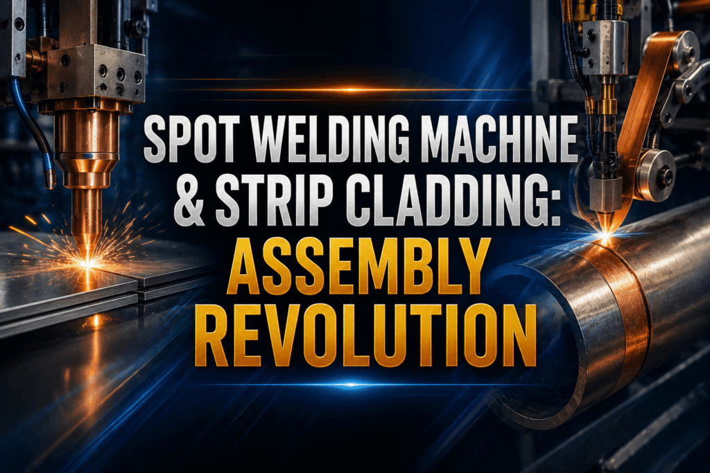
How Automatic Spot Welding and Strip Cladding Machines Transform Automotive and Sheet Metal Assemblies The manufacturing industry is undergoing a massive paradigm shift. Consumer demand for safer cars, lighter components, and durable pressure vessels is skyrocketing. Because of this, standard manual fabrication processes are no longer sufficient. Modern assembly lines require absolute precision, high structural integrity, and exceptional speed. To achieve these metrics, forward-thinking manufacturers are moving away from traditional techniques. Instead, they are rapidly adopting a highly specialized, automatic welding machine to anchor their production infrastructure. At the center of this industrial evolution is the heavy-duty spot welding machine. This piece of machinery serves as a primary pillar in high-speed sheet metal fabrication. It works hand in hand with the advanced strip cladding device, an essential asset used to provide robust surface protection against corrosion and extreme heat. When industrial operations combine these two manufacturing powerhouses, the results are deeply transformative. Operational bottlenecks vanish, material waste plummets, and joint reliability reaches flawless standards. For modern enterprises aiming to secure a decisive edge in competitive markets, understanding how these automated systems interact is critical. This comprehensive guide details how automated resistance welding and heavy-duty surface cladding systems are rewriting the rules of the automotive and sheet metal sectors. The Core Dynamics of Modern Spot Welding Machines in Sheet Metal Fabrication To appreciate the massive impact of automated manufacturing, you must first understand the fundamental core of the technology. The standard industrial spot welding machine operates on the core principles of electrical resistance. It passes a high-volume electrical current directly through the materials being joined. The natural resistance of the metal pieces generates intense localized heat, melting the contact points instantly. Once the current stops, copper-alloy electrodes apply mechanical pressure to fuse the molten metal into a flawless, uniform nugget. In high-volume sheet metal fabrication, consistency is the defining metric of profitability. Manual operations frequently suffer from human fatigue, misaligned sheet metal joints, and unpredictable heat input. An automated resistance welder entirely eliminates these costly human variables. Built-in microprocessors continuously monitor and modulate electrical output, force application, and cycle times in real time. This level of digital oversight guarantees that every single weld matches the structural properties of the previous one. This eliminates internal defects like excessive spatter or weak, under-penetrated joints. Additionally, automated systems eliminate the need for secondary grinding or clean-up work, allowing parts to move directly to the next stage of assembly. Accelerating Production via Automotive Welding Automation The global automotive manufacturing industry is highly demanding. Vehicle assembly lines regularly handle thousands of intricate parts every day, and each component demands strict compliance with international safety protocols. In this environment, automotive welding automation is not just an optional luxury; it is a fundamental operational necessity. Structural sub-assemblies—such as door pillars, floor pans, firewalls, and bracket assemblies—rely heavily on rapid, repeatable joints to ensure the crashworthiness of the final vehicle. Integrating an automatic welding machine into an automotive production line delivers immediate, compounding advantages: Furthermore, the introduction of ultra-high-strength steels (UHSS) and lightweight aluminum alloys in car designs introduces significant manufacturing challenges. These specialty materials react poorly to prolonged, uneven heat exposure. Advanced resistance welding setups solve this problem. They deliver short, high-energy bursts coupled with precise mechanical force, allowing factories to assemble lightweight, fuel-efficient vehicles without sacrificing passenger safety. Demystifying the Strip Cladding Device: Protecting Components Under Stress While joining two pieces of sheet metal together is vital, protecting those components from harsh environments is equally important. This is where the specialized strip cladding device proves its immense value. Unlike a traditional spot welding machine that joins distinct parts edge-to-edge, cladding focuses entirely on surface enhancement. It applies a thick, uniform layer of high-performance alloy onto a cheaper base metal, creating a highly resilient protective shield. This process typically relies on advanced techniques such as the automated electroslag cladding process or submerged arc welding (SAW). During operation, a wide metal strip—frequently made of stainless steel or a nickel-based alloy—is continuously fed onto the surface of the component. The machinery melts the strip overlay uniformly, bonding it perfectly to the heavy base metal with minimal dilution. This advanced surface treatment is highly valued across demanding industries, including: By utilizing a high-efficiency cladding system, engineering teams can manufacture the main body of a large pressure vessel out of standard, cost-effective carbon steel. They can then clad only the vulnerable interior walls with a premium, corrosion-resistant alloy. This balanced manufacturing approach saves thousands of dollars in raw material costs while extending the working lifespan of the equipment by decades. Spot Welding vs. Strip Cladding: Understanding Their Roles To build a truly optimized manufacturing workflow, production engineers must clearly distinguish between these two core automated processes. While both utilize electrical energy to melt and fuse metal, their operational goals, mechanical configurations, and everyday factory applications are completely different. Operational Criteria Spot Welding Machine Technology Strip Cladding Device System Primary Industrial Objective Securely fuses overlapping sheets of metal at specific, high-strength contact points. Applies an even, continuous protective overlay across a broad component surface. Material Thickness Focus Optimized for thin to medium gauges, primarily in sheet metal fabrication. Designed for heavy-duty plate surfaces and large-diameter industrial piping. Consumable Consumption Uses non-consumable copper-alloy electrodes to apply localized pressure. Consumes wide alloy metal strips along with specialized protective fluxes. Common Factory Applications Vehicle body frames, appliance enclosures, and specialized bracket assemblies. Inside walls of chemical reactors, heavy pressure vessels, and marine components. Integrating these two distinct technologies into a unified production network allows industrial facilities to cover all bases. They can build strong, lightweight structures using automated resistance spot welding, and protect heavy-duty, high-stress components with precise surface cladding. Exploring Advanced Variants: The Projection Welding Machine As production demands grow more complex, standard spot welding methods sometimes run into physical limits. For example, joining thick nuts, heavy threaded studs, or intricate brackets to ultra-thin sheet metal can cause uneven heat distribution, often resulting in surface deformities or weak joints. To overcome these specific manufacturing

tig welding machine
Uncategorized

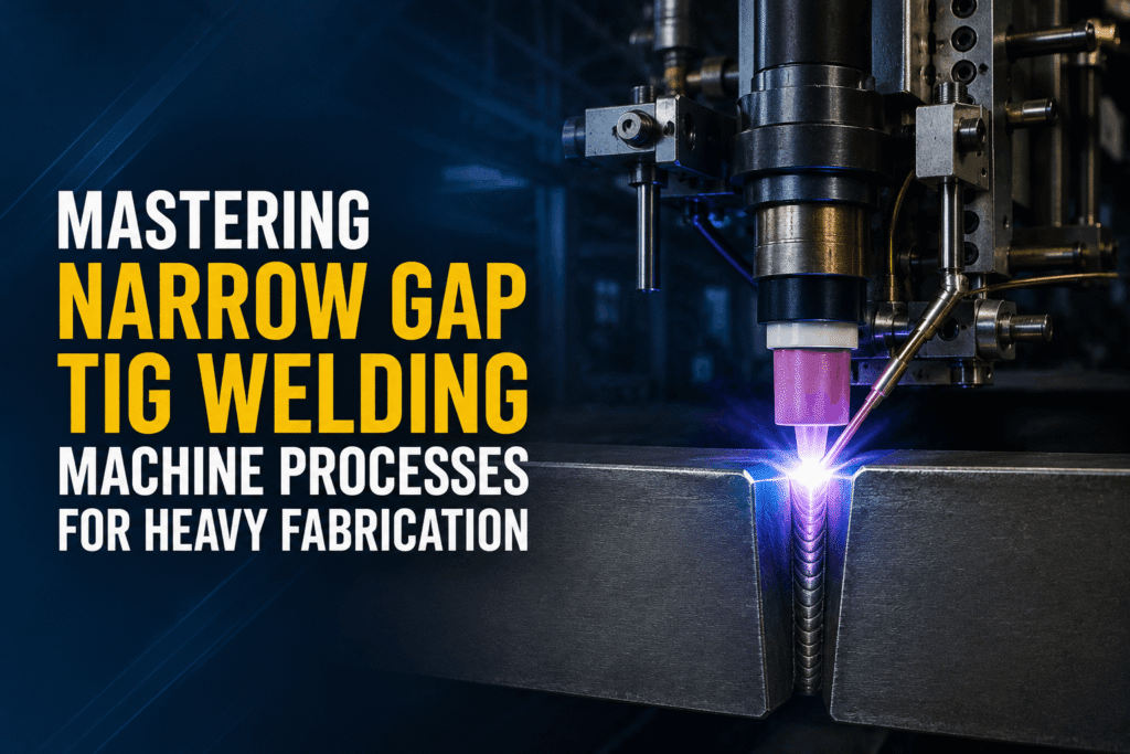
Mastering Narrow Gap TIG Welding Machine Processes for Heavy Fabrication

Mastering Narrow Gap TIG Welding Machine Processes for Heavy Fabrication Modern heavy manufacturing setups constantly face structural and logistical challenges when attempting to efficiently fuse thick metallic sections. Traditional beveling protocols necessitate broad joint configurations that demand massive amounts of consumable filler material and extreme thermal expenditure. Consequently, structural manufacturing facilities run into elevated cycle timelines, structural deformation, and high production operating costs. To circumvent these expensive structural pitfalls, advanced heavy infrastructure engineering teams are shifting away from manual configurations. They are adopting mechanized systems built to deliver high-quality root and filler passes within highly constrained operational tolerances. Understanding how to orchestrate a high-performance tig welding machine setup within a tight joint profile is essential for achieving deep, flaw-free root fusion in structural steels and high-alloy metals. When dealing with material sections exceeding 50 mm, traditional joint setups fall short under stringent quality inspections. This comprehensive manual explores how Mastering Narrow Gap TIG Welding Machine Processes for Heavy Fabrication can transform your production floor. We will break down operational mechanics, metallurgical considerations, and automation strategies designed to help your workshop operate at peak efficiency. Section 1: Decoding the Industrial TIG Welder for Narrow Trench Applications What is TIG Welding Machine Engineering in Specialized Joint Fields? To properly integrate mechanized welding systems into production lines, you must first understand the fundamental engineering of an industrial tig welder. At its core, the Gas Tungsten Arc Welding (GTAW) system establishes a highly stable electrical arc between a non-consumable tungsten electrode and the metal workpiece. In standard setups, this arc is wide open, allowing manual operators sufficient room to manipulate the torch profile. However, inside a narrow groove—where joint sidewalls are separated by an tight width of just 9 to 10 millimeters—a standard manual configuration becomes completely unfeasible. When analyzing what is tig welding machine technology in modern heavy fabrication, it refers to specialized systems engineered to maintain an incredibly stable arc column deep within a confined metal channel. The process relies on a precision-designed torch nozzle that fits cleanly inside narrow joint sidewalls without short-circuiting. By switching from a standard wide V-groove to an advanced parallel or near-parallel joint configuration, you dramatically reduce the total volume of weld metal needed to fill the joint. Core Mechanics of the Narrow Gap TIG Welding Subsystem Operating inside a tight groove requires a specialized narrow gap tig welding torch assembly. Standard torches cannot operate at these depths because the gas cup would hit the top edges of the plates, preventing the arc from reaching the root. Specialized narrow groove systems utilize extended, low-profile water-cooled torches that insert directly into the deep, parallel seam. A primary technical obstacle when welding deep inside a 10 mm channel is preventing the electrical arc from wandering or snapping to the adjacent sidewalls. Because electricity follows the path of least resistance, the arc naturally tends to jump to the closest vertical sidewall rather than penetrating straight down into the joint root. Advanced systems resolve this physical limitation by implementing mechanized electrode oscillation. By swinging or rotating the arc precisely between the left, middle, and right sidewall positions, the system guarantees complete tie-ins and defect-free root fusion. Section 2: Technical Breakdown of the Narrow Gap TIG Process Thermal Advantages of the Mechanized TIG Process The specialized tig process offers major metallurgical benefits, particularly when handling heavy structural sections that are sensitive to excessive thermal input. Traditional multi-pass processes expose heavy plates to repeated, prolonged thermal cycles, which can expand the heat-affected zone (HAZ) and degrade the base material’s grain boundaries. Because a narrow groove configuration requires considerably fewer total passes to fill the seam, the overall thermal load on the assembly is significantly lower. This precise, localized heat control reduces residual stress fields and eliminates the structural distortion that typically warps thick metal plates during fabrication. Furthermore, because the automated system deposits thin, uniform weld beads sequentially, the heat from each consecutive pass acts as a localized thermal treatment for the layers underneath. This continuous, controlled reheating refines the internal grain profile, maximizing impact toughness and tensile strength across the entire cross-section of the weld joint. Key Specifications of High-Performance Systems Implementing this advanced technology requires rigorous adherence to precise operating envelopes. The table below details the performance parameters of an automated heavy production setup: Process Parameter Industrial Production Value Range Maximum Structural Plate Thickness 150 mm (Horizontal Position) up to 600 mm (Flat Position) Operational Groove Seam Width 9 mm to 10 mm Automated Wire Deposition Speed 35 to 60 grams per minute Linear System Travel Speed 50 to 300 millimeters per minute Pass Configuration Structure Single pass per layer Filler Wire Diameter Selection 1.2 mm Automated Wire Feed Delivery Rate 0.2 to 6.8 meters per minute Section 3: Essential Equipment Components for Industrial Fabrication 1. Advanced Automated Arc Shielding Systems Maintaining absolute weld puddle purity at deep production levels requires highly reliable gas coverage. Standard gas cups cannot deliver adequate coverage deep within a 150 mm structural joint. To solve this, automated manufacturing systems leverage specialized argon welding machine components featuring customized trailing gas shields. Pure argon gas flows through independent internal channels within the low-profile torch, providing full coverage over the molten puddle. This specialized gas delivery isolates the active weld zone from atmospheric oxygen and nitrogen, preventing the formation of micro-porosity defects deep within the joint structure. 2. High-Precision Mechanical Torch Oscillators Achieving complete tie-ins along the vertical side walls of a narrow joint requires highly precise torch oscillation. Advanced production systems integrate mechanical or magnetic oscillation modules that move the tungsten tip according to precise timing parameters. The torch is programmed to dwell briefly at the left sidewall, move rapidly across the center, and dwell at the right sidewall. This precise motion distribution ensures uniform heat delivery, completely eliminating lack-of-fusion defects along the vertical edges of the channel. 3. Integrated Dynamic Arc Voltage Control (AVC) In deep, narrow joints, even minor variations in surface height or distance can disrupt arc stability, causing the tungsten electrode to

welding automation solutions
Uncategorized

How to Choose the Right Industrial Welding Machine: A Complete Buyer’s Guide

How to Choose the Right Industrial Welding Machine: A Complete Buyer’s Guide Selecting the proper equipment for heavy manufacturing operations is a decision that dictates long-term profitability, product quality, and operational safety. In the modern fabrication landscape, making an accurate industrial welding machine selection requires balancing multiple complex variables. A wrong equipment purchase can easily lead to structural joint failures, unexpected production bottlenecks, and costly operational downtime. Conversely, aligning your choice with your exact material specifications and volume targets can dramatically boost throughput and cut scrap rates. This comprehensive guide breaks down the essential factors needed to execute a flawless industrial welding machine selection. From decoding technical specifications to determining the right level of automation for your floor, we will outline the blueprint for a smart procurement strategy. Whether you are looking to upgrade a single station or fully overhaul an automated production assembly line, this resource is designed to help you make an informed decision. 1. Core Heavy-Duty Welding Processes and Equipment Types The foundation of sound industrial welding machine selection begins with identifying the most suitable welding methodology for your application. Each major process offers distinctive performance characteristics tailored to specific material types and structural demands. Submerged Arc Welding (SAW) Power Sources For thick structural steel fabrication, pressure vessels, and heavy infrastructure projects, Submerged Arc Welding remains the undisputed standard. SAW systems utilize a granular flux layer to blanket the molten weld pool, completely eliminating arc flash and hazardous smoke while delivering exceptionally deep penetration. Heavy Industrial TIG and MIG Welding Systems Gas Metal Arc Welding (MIG) and Gas Tungsten Arc Welding (TIG) are the backbones of modern precision fabrication. Advanced Multi-Process Systems and Specialized Technology Modern production challenges often require more than conventional equipment can provide. Advanced configurations combine multiple capabilities to optimize floor space and capital expenditures: 2. Analyzing Material Specifications and Structural Parameters Selecting an industrial system based solely on amperage ratings without examining metallurgical demands can lead to severe quality issues. Your material profile directly dictates the required power architecture of the machine. Material Type Recommended Welding Process Power Source Requirements Critical Selection Factor Heavy Mild/Structural Steel Submerged Arc Welding (SAW) / Heavy MIG High Amperage (600A-1200A+), High Duty Cycle Deep penetration, continuous thermal delivery Stainless Steel & Superalloys TIG / Narrow Gap TIG / Cladding Systems Precision Current Control, Low Amperage Stability Precise heat-input management, shielding gas integrity Aluminum Alloys Advanced MIG / Squarewave AC TIG AC Balance Control, High-Frequency Arc Start Oxide layer cleaning action, rapid heat dissipation Material Thickness and Thermal Input Management The thickness of your primary base metal determines the required current capacity and thermal threshold of your power source. Thin sheet metals require precision low-amperage control to prevent burn-through, while structural steel beams and thick-walled vessels demand consistent, high-amperage output to ensure complete joint fusion. For heavy-duty applications exceeding 20mm in thickness, standard manual methods quickly become inefficient. In these scenarios, sourcing machines designed for heavy multi-pass operations or automated strip cladding becomes essential to ensure uniform structural integrity. 3. Production Volume, Duty Cycle, and Power Distribution An industrial power source must withstand rigorous operating conditions without overheating or shutting down mid-weld. Evaluating duty cycle and plant power infrastructure is critical to avoiding premature component failure. The 100% Duty Cycle Benchmark In industrial manufacturing, duty cycles are measured over a 10-minute operation window. While light fabrication tools operate at a 40% or 60% duty cycle, high-volume industrial lines require power sources capable of operating at a 100% duty cycle at maximum amperage. This allows for continuous welding without thermal safety shut-offs, maximizing daily output. Industrial Electrical Infrastructure Compatibility Industrial facilities utilize three-phase electrical power (typically 380V, 415V, or 440V). It is essential to ensure that your chosen welding system features robust voltage fluctuation compensation. Fluctuations in the plant grid can alter arc characteristics, leading to porosity or lack of fusion. High-tier industrial units include active electronic stabilization to maintain arc consistency even during peak factory power demands. 4. Selecting the Optimal Automation Level for Your Shop Floor Transitioning from manual welding to automated systems is one of the most effective ways to lower production costs and solve skilled labor shortages. The right degree of automation depends heavily on your part volume and consistency. Semi-Automated vs. Fully Automated Systems Dedicated Special Purpose Machines (SPMs) When a factory produces identical components continuously, standard articulated robots can sometimes be less efficient than a custom Special Purpose Machine (SPM). For instance, dedicated conveyor roller manufacturing lines integrate pressing, cutting, and dual-torch welding into a single streamlined process. These specialized systems deliver far higher throughput and lower per-unit cycle times than general-purpose robotic arms. Integrating Material Handling and Positioning Equipment An automated power source is only as efficient as its positioning system. Integrating column-and-boom manipulators, heavy-duty welding rotators, and precise positioners ensures that the weld joint always remains in the optimal flat position. This integration minimizes defect rates and maximizes deposition speeds. 5. Industrial Application Profiles and Heavy Sector Requirements Different industries operate under distinct regulatory frameworks and structural standards. Your industrial welding machine selection must align with the specific compliance demands of your target market. Pressure Vessels, Boilers, and Heavy Chemical Reactors Fabricating equipment for high-pressure environments requires strict adherence to international codes like ASME Section VIII. Welds must pass 100% radiographic and ultrasonic non-destructive testing (NDT). To achieve this standard consistently, manufacturers rely heavily on automated Narrow Gap SAW and specialized corrosion-resistant cladding systems to avoid manual defects. Infrastructure, Pre-Engineered Buildings (PEBs), and Railway Girders The infrastructure sector requires long, uninterrupted structural fillet and groove welds. Equipment configurations for this space typically feature multi-arc tractor setups or dedicated gantry welding systems. These allow for rapid deposition across long steel girders while maintaining minimal distortion. Heavy Equipment Parts and Automotive Sub-Assemblies The high-speed nature of the automotive and heavy machinery sectors requires robust resistance welding systems. Utilizing high-capacity Single-Phase AC or Medium Frequency Direct Current (MFDC) spot and projection welders allows for rapid, high-strength joining of sheet metal and brackets without

Submerged Arc Welding Machine Manufacturer
Uncategorized

Best Submerged Arc Welding Machine Manufacturer in India: What to Look For

Best Submerged Arc Welding Machine Manufacturer in India: What to Look For In the rapidly expanding industrial landscape, heavy fabrication demands precision, speed, and uncompromising structural integrity. Whether you are building massive pressure vessels, constructing heavy-duty railway girders, or shaping Pre-Engineered Buildings (PEBs), your equipment choice dictates your bottom line. Consequently, finding the right Submerged Arc Welding Machine Manufacturer is one of the most critical decisions your engineering team will make. The Submerged Arc Welding (SAW) process relies on a granular flux blanket to shield the welding zone from atmospheric contamination. This method provides exceptionally deep penetration, minimal smoke, and clean, high-quality deposits. However, to unlock these advantages consistently, you need robust equipment backed by advanced technology. Selecting a reliable Submerged Arc Welding Machine Manufacturer in India goes far beyond looking at a simple price tag. It requires a deep dive into engineering standards, technological collaborations, and real-world application support. Let us break down exactly what you must look for when choosing your industrial fabrication partner. Why Choosing the Right Manufacturer Impacts Production Quality Heavy manufacturing leaves zero room for error. A single defect in a heavy-duty weld joint can delay timelines, skyrocket repair costs, or compromise structural safety. Therefore, your choice of heavy-duty welding equipment acts as the literal backbone of your workshop. 1. Advanced Technology Integration The industrial sector has transitioned away from legacy systems. Today, standard workshops require high-efficiency setups that reduce manual intervention. When evaluating an industrial provider, look closely at their technical heritage. For instance, manufacturers utilizing specialized design partnerships, such as the globally recognized Panasonic technology framework, consistently deliver exceptional reliability. This advanced integration translates directly into stable arc performance, minimal downtime, and uniform bead profiles across miles of heavy steel fabrication. 2. Industry-Specific Customization No two fabrication projects are exactly alike. A standard power source might suffice for simple structural steel, but complex pressure vessels require distinct wave-control configurations. A premier Submerged Arc Welding Machine Manufacturer should provide a wide array of specialized options, including: Core Criteria to Evaluate a Submerged Arc Welding Machine Manufacturer When sorting through potential equipment suppliers in India, you must look past basic marketing claims. Use these technical and structural indicators to evaluate true engineering competence. Engineering Footprint and Domestic Presence Is the supplier a mere distributor, or do they possess a fully realized manufacturing setup? A true 100% Indian company with specialized roots can understand local power grid fluctuations, operating environments, and regulatory standards. For example, a dedicated facility located in a manufacturing hub like Pune, Maharashtra, serves as an ideal indicator of structural permanence. Furthermore, a manufacturer with an active on-site demo center allows your technical teams to test advanced configurations before finalizing capital expenditures. Testing technologies like Narrow Gap SAW or advanced Strip Cladding Devices on your specific metal alloys removes all guesswork from the procurement loop. Comprehensive Product Portfolio A reputable heavy-duty welding equipment provider shouldn’t just sell power sources; they should deliver comprehensive automation workflows. If your operations grow, you will likely need to expand into adjacent automated systems. Choosing a partner who designs complementary technology ensures seamless long-term scaling. Ensure your chosen manufacturer offers a robust spectrum of industrial systems: Technical Features Your Submerged Arc Welding Systems Must Have Investing in heavy industrial machinery requires a checklist of non-negotiable technical features. If a manufacturer cannot offer these baseline capabilities, your production efficiency will inevitably lag. 1. Robust Duty Cycle and Thermal Rating For continuous industrial fabrication, a 100% duty cycle at maximum current output is mandatory. Your machines must run effortlessly through long shifts without overheating or triggering thermal shutdowns. High-grade thyristor-controlled systems or digital inverter modules must be housed in dust-resistant, well-ventilated enclosures designed specifically for heavy-duty metal workshops. 2. Seamless Integration with Welding Automation Solutions Manual SAW setups are increasingly rare. Modern factories rely on tractor units, welding booms, column-and-boom manipulators, and gantry systems. The power source you buy must feature flexible analog or digital communication interfaces to connect seamlessly with broader welding automation solutions. Without proper interface protocols, integrating the machine into a robotic cell or a heavy-duty automated girder line becomes an engineering nightmare. 3. Precision Wire Feeding Mechanisms The quality of a submerged arc weld relies heavily on consistent wire delivery. Fluctuations in wire speed lead to variations in bead width and penetration depth. Look for heavy-duty, four-roll drive wire feeders that prevent slippage even when pulling thick wire diameters from massive wire spools over extended distances. Maximizing Efficiency with Advanced Welding Processes A visionary Submerged Arc Welding Machine Manufacturer does not stop at standard open-arc setups. They continually innovate, driving efficiency through specialized processes designed for high-stress manufacturing sectors. Narrow Gap Submerged Arc Welding (SAW) When welding exceptionally thick plates—such as those used in nuclear reactors, massive pressure vessels, or heavy defense infrastructure—traditional V-groove preparations require an immense volume of filler metal. This takes countless passes and consumes massive amounts of time and raw materials. By upgrading to a specialized system like the Narrow Gap SAW, you can dramatically reduce the groove angle. This minimizes the total volume of weld metal required, slashes heating cycles, and drastically reduces overall fabrication time while maintaining immaculate radiographic quality. Automated Strip Cladding In the chemical, oil, and gas sectors, base metals must often be protected against corrosive substances. Instead of fabricating entire structures out of expensive corrosion-resistant alloys, engineers use a cost-effective alternative: overlaying a thick carbon steel plate with a protective layer using an automated Strip Cladding Device. A top-tier industrial manufacturer provides the precise power controls and specialized cladding heads required to deposit uniform, defect-free anti-corrosive linings efficiently. Industrial Applications: Who Relies on Premium SAW Equipment? To confirm that a manufacturer’s machinery can withstand your operational demands, look at the industries they actively serve. Heavy industrial environments require distinct performance characteristics that only specialized equipment can deliver. Post-Purchase Support: The True Mark of a Top Manufacturer The relationship with your Submerged Arc Welding Machine Manufacturer should never end when the equipment is delivered. In heavy manufacturing,

industrial welding automation
Uncategorized

Industrial Welding Automation Solutions: How to Select the Right System

Industrial Welding Automation Solutions: How to Select the Right System The modern industrial manufacturing environment is shifting rapidly away from slow, inconsistent manual operations toward highly optimized, high-throughput systems. At the center of this structural shift is industrial welding automation, a technological evolution that turns a historically labor-dependent task into a highly predictable, repeatable, and profitable asset. For large-scale structural fabricators, pressure vessel manufacturers, and automotive suppliers, the core challenge is no longer deciding if you should automate, but identifying how to select the precise automatic welding solutions that match your shop floor’s specific operational needs. Implementing a generic setup without evaluating your exact mechanical requirements can result in costly workflow integration errors, underutilized hardware, and long payback cycles. Selecting the right welding automation machine involves aligning production volume, geometric complexity, metallurgical demands, and capital investment budgets with the right hardware configuration. Making a flawed choice can hurt your bottom line. Conversely, a carefully matched setup can slash cycles times by up to 80% while ensuring structural reliability. This comprehensive technical guide breaks down the essential criteria for choosing an automated welding system. It highlights advanced arc processes, mechanical tracking mechanisms, and application frameworks designed to maximize structural production efficiency. 1. Analyze Your Production Volume and Product Mix Before evaluating specific welding power sources or robotic articulation axes, you must conduct an exhaustive analysis of your current and projected production profiles. Industrial fabrication generally falls into two distinct operational paradigms: High-Volume, Low-Mix (HVLM) If your facility produces thousands of identical structural components with little to no dimensional variation, your operations are perfectly suited for Dedicated Automation or Special Purpose Machines (SPMs). These systems are engineered to perform specific, repetitive tasks with maximum speed. A prime example is the heavy-duty material handling sector. Producing conveyor networks demands thousands of uniform idler rollers. Trying to execute this with disjointed manual setups creates massive floor bottlenecks. By employing an end-to-end integrated line—such as a specialized idler roller manufacturing machine that handles automated pipe cutting, double-ended boring, housing assembly, and synchronized perimeter welding—raw steel tubing is systematically converted into a finished conveyor component with minimal operator intervention. Low-Volume, High-Mix (LVHM) When your shop floor regularly manages diverse batch runs with shifting geometries, custom lengths, and variable joint positions, it requires the agility of Programmable Robotic Welding Cells. These configurations feature articulated multi-axis arms integrated with intelligent controller interfaces. They allow engineers to quickly swap out software programs or leverage offline tracking systems to adapt to structural design changes without physical re-tooling. 2. Match the Automation System to Your Primary Arc Process Every welding process introduces distinct thermal, electrical, and mechanical forces to the joint area. Your choice of automation hardware must be tailored to handle the specific arc delivery system required for your material thickness and performance specifications. Submerged Arc Welding (SAW) Automation For heavy infrastructure, thick plate joining, and massive pressure vessel fabrication, Submerged Arc Welding remains the standard for high-deposition performance. Because SAW utilizes a continuous, consumable bare wire electrode blanketed under a layer of granular, fusible flux, the system generates immense heat and high deposition rates without exposing operators to bright arc flash or dangerous fumes. Automating this process requires robust, vibration-free mechanical rigs. Integrating heavy-duty power sources with specialized columns, booms, and turning rolls allows manufacturers to lay down multi-pass welds on thick-walled cylinders seamlessly. This approach eliminates the risk of interlaminar defects and surface porosity that frequently disrupt manual operations. Learn more about optimizing these setups in our complete guide for heavy fabrication industries. Automated TIG and Deep-Penetration TIG (DP-TIG) When working with stainless steel, exotic alloys, or precision aerospace assemblies, Gas Tungsten Arc Welding (GTAW/TIG) is preferred for its exceptional metallurgical purity and aesthetic refinement. However, traditional automated TIG can struggle with slower travel speeds and limited penetration depths on thicker materials. Advanced systems overcome these limitations through deep-penetration technologies like DP-TIG. By implementing specialized high-density inverter power supplies and custom torch cooling setups, automated DP-TIG systems can achieve single-pass, full-penetration welds on thick alloy plates without complex edge beveling. This drastically lowers shielding gas consumption and cuts filler wire costs. Automated MIG/MAG (GMAW) and Narrow Gap Systems Gas Metal Arc Welding (GMAW/MIG) is highly versatile and easily automated across structural steel projects. When fabricating thick-walled structural members, traditional V-groove preparations require substantial volume fills, driving up wire consumption and total heat input. To optimize material costs and improve mechanical properties, look for specialized Narrow Gap MIG systems. These specialized welding automation solutions use precise torch oscillation and advanced wire feeding mechanics to operate within narrow groove preparations. This dramatically reduces total weld volume and prevents multi-pass thermal warping. 3. Evaluate the Mechanical Manipulators and Positioning Infrastructure An automated welding setup is only as accurate as its mechanical delivery system. Even the most advanced power source cannot compensate for physical vibrations, jerky cross-slides, or unstable workpieces. To achieve true automated precision, your system must incorporate high-end mechanical positioning accessories. 4. Invest in Intelligent Tracking and Sensing Systems In real-world fabrication settings, component parts rarely match the perfect geometries found in CAD models. Thermal distortion from previous passes, minor pre-weld fit-up variations, and structural plate warping can all push the actual joint path away from the programmed trajectory. To maintain flawless quality without constant operator adjustments, your automated systems should feature modern, integrated tracking sensors. Laser-Guided Vision Systems These optical sensors mount just ahead of the welding torch, projecting a laser line across the joint profile. The system captures the reflected light profile via a high-speed camera, analyzing joint width, root gaps, and alignment offsets in real time. The digital controller automatically adjusts the motorized cross-slides, ensuring the electrode stays perfectly centered within the groove. Tactile Seam Tracking For straightforward applications or harsh environments with heavy smoke and dust, mechanical tactile tracking offers a reliable, low-maintenance alternative. A durable probe rides directly within the seam, mechanically triggering micro-switches that signal the positioning slides to correct for physical height and lateral deviations on the fly. 5. Prioritize Controller Usability

automated welding machine
Uncategorized

Automatic Welding Machine vs Manual Welding: Which Is Better for Industry?

Automatic Welding Machine vs Manual Welding: Which Is Better for Industry? The manufacturing landscape is undergoing a massive shift driven by technological advancement. Industrial production demands speed, precision, and cost-effectiveness to remain competitive in a crowded global marketplace. At the center of this evolution is a fundamental decision that workshop owners, production managers, and enterprise executives must make: Automatic Welding Machine vs Manual Welding: Which Is Better for Industry? Choosing the correct fabrication methodology directly impacts your operational throughput, labor dynamics, and bottom-line profitability. For decades, traditional manual welding has been the bedrock of structural fabrication, custom manufacturing, and heavy industrial assembly. However, as global market demands put a premium on rapid scaling and flawless consistency, the industrial reliance on the classic automatic welding machine has surged. Deciding between these two paths is not merely a matter of comparing tools; it requires a deep, strategic analysis of production volume, structural requirements, and long-term capital expenditure. This comprehensive guide analyzes the functional mechanisms, economic realities, and hidden trade-offs of automated versus manual welding processes. By exploring how each system performs under industrial pressures, you will gain the clarity required to make an informed, forward-looking investment for your facility. The Fundamentals of Modern Industrial Welding To understand which approach suits your operations, we must first break down the technological definitions and practical workflows that separate automated systems from manual craftsmanship. Defining the Automatic Welding Machine An automatic welding machine refers to an integrated system where mechanical components, electronic sensors, and programmable logic controllers (PLCs) execute the welding process without continuous human intervention. Once a technician configures the operational parameters—such as travel speed, voltage, wire feed rate, and torch positioning—the machine executes high-precision welds with absolute uniformity. These setups often incorporate specialized sub-components, such as an advanced welding oscillator, which mechanically weaves the welding torch across a joint. This automated oscillation mimics the complex hand movements of a master welder but maintains a level of geometric consistency that no human can duplicate over an eight-hour shift. Defining Manual Welding Processes Manual welding relies entirely on the physical dexterity, visual judgment, and spatial awareness of a human operator. Processes like Shielded Metal Arc Welding (SMAW/Stick), Gas Tungsten Arc Welding (GTAW/TIG), and manual Gas Metal Arc Welding (GMAW/MIG) require the welder to manually strike the arc, feed the filler material, and guide the torch along the weld seam. While manual welding offers unparalleled adaptability in tight spaces or on highly complex, non-repetitive geometries, it is inherently limited by human fatigue, cognitive drift, and physical variation. Automatic Welding Machine vs Manual Welding: Direct Comparison Feature / Metric Automatic Welding Machine Manual Welding Production Speed & Output Extremely high; continuous operation with zero fatigue. Limited by human endurance, rest breaks, and setup times. Weld Quality & Consistency Flawless, repeatable welds; minimal reject rates. Highly dependent on individual welder skill and fatigue levels. Initial Capital Investment High upfront cost for equipment, software, and integration. Low initial cost; requires basic power sources and safety gear. Long-Term Operational Costs Low per-part cost; optimized consumable and gas usage. High per-part cost due to ongoing labor rates and material waste. Operational Flexibility Best suited for standardized, high-volume, repetitive tasks. Exceptionally flexible; adapts instantly to varied job types. Safety & Risk Profile Isolates operators from toxic fumes, radiation, and heat. High exposure to weld spatter, hazardous gases, and flash burns. Core Advantages of an Automatic Welding Machine When analyzing an industrial transition to automation, the advantages extend far beyond simply replacing manual labor. Automated infrastructure redefines the entire production paradigm through several key metrics: 1. Maximizing Throughput and Production Speed In high-volume manufacturing environments, time is quite literally currency. An automatic welding machine operates at travel speeds that far outpace even the fastest human operators. Because automated systems do not experience physical fatigue, they can maintain maximum operational speeds continuously across multiple shifts. Furthermore, automation minimizes the non-productive downtime typically spent changing electrodes, cleaning slag, or readjusting positioning between tasks. By combining automated welding torches with specialized welding rotators, large cylindrical vessels or heavy piping can be spun smoothly beneath a fixed welding head, creating a continuous, uninterrupted workflow that slashes production cycle times by up to 70%. 2. Flawless Structural Integrity and Repeatability In industries such as aerospace, automotive manufacturing, and pressure vessel fabrication, a single weld failure can lead to catastrophic structural accidents or costly legal liabilities. Automated systems remove human variability from the equation. When an automated machine is programmed to execute a specific seam, it delivers identical bead profiles, penetration depths, and microstructural properties every single time. This level of precision minimizes internal weld defects like porosity, lack of fusion, or undercut, ensuring your products easily pass stringent non-destructive testing (NDT) protocols. 3. Substantial Reduction in Material Waste and Consumable Costs Manual welding is notorious for material variance. A welder may inadvertently over-weld a joint, using more filler wire and shielding gas than the engineering specifications require. Over time, these small discrepancies accumulate into thousands of dollars in wasted materials. An automatic welding machine consumes exactly the calculated volume of wire, flux, or gas required for the joint design. Additionally, because automated welds rarely fail quality checks, companies can virtually eliminate the expenses associated with grinding out, re-prepping, and re-welding defective components. Understanding the Limitations of Automated Systems Despite its profound operational advantages, automation is not a universal solution for every fabrication business. Understanding its constraints is critical for preventing misallocated capital. The Value Proposition of Manual Welding in Modern Industry While automation dominates high-volume production lines, manual welding remains a vital and irreplaceable asset across various industrial sectors. Unmatched On-Site Flexibility and Mobility The greatest strength of manual welding is its mobility. A field welder equipped with a portable inverter power source can operate on structural job sites, offshore oil platforms, or remote pipeline networks. Humans can adapt instantly to unpredictable real-world variables, adjusting their torch angle, travel speed, and technique to accommodate shifting wind conditions, awkward physical angles, or varying root gap dimensions. Low Entry Costs

Submerged Arc Welding
Uncategorized

Submerged Arc Welding (SAW): Complete Guide for Heavy Fabrication Industries

Submerged Arc Welding (SAW): Complete Guide for Heavy Fabrication Industries The demands of modern industrial manufacturing require structural joints that offer uncompromising strength, absolute metallurgical integrity, and high-speed production. For sectors dealing with thick-plate structural steel, heavy pressure vessels, marine vessels, and wind tower foundations, conventional manual welding methods are simply insufficient. This is where Submerged Arc Welding (SAW) asserts itself as the undisputed backbone of heavy engineering. By shielding the electrical arc beneath a deep blanket of granular, fusible flux, the Submerged Arc Welding process eliminates the environmental hazards of open-arc welding—such as intense ultraviolet radiation, blinding sparks, and toxic fumes—while delivering unmatched deposition rates and deep joint penetration. To achieve profitability and fulfill strict structural codes, heavy fabrication industries rely on cutting-edge systems. Kaiyuan Welding & Cutting Automation India Pvt Ltd provides industrial manufacturing with state-of-the-art Submerged Arc Welding solutions. Designed with proprietary innovations and Panasonic technology, these systems offer high reliability and automation capabilities tailored for the structural steel and heavy engineering landscape. What is Submerged Arc Welding (SAW)? Submerged Arc Welding is an automated or semi-automated wire-feed welding process designed for making continuous, long longitudinal or circumferential joints on thick metallic plates. Unlike Gas Metal Arc Welding (GMAW) or Shielded Metal Arc Welding (SMAW), where the arc is exposed to the ambient atmosphere or protected by a localized shielding gas envelope, the SAW process operates entirely beneath an engineered mineral flux layer. The Core Mechanics of the Process During operation, a continuously fed solid or cored wire electrode is directed into the joint prep area. Concurrently, a precise stream of granular flux is deposited from an attached flux hopper directly ahead of the advancing welding head. The electrical arc strikes between the tip of the electrode wire and the base metal workpiece, completely hidden beneath this granular bed. The intense heat generated by the concentrated high-amperage current melts a portion of the electrode, the base metal plates, and a localized zone of the surrounding flux. This creates a highly stable, molten puddle. As the welding head moves along the seam at a constant travel speed, the molten metal cools and solidifies into a exceptionally clean, high-strength joint weld bead. The molten flux floats to the surface, forming a protective, easily detachable layer of solidified slag that prevents atmospheric contamination and controls the cooling rate of the weldment. Key Components of an Industrial SAW System An industrial-grade Submerged Arc Welding installation requires specialized hardware engineered to withstand severe environments and deliver continuous duty cycles. 1. Robust SAW Power Sources The foundation of any high-penetration welding cell is its power source. Industrial fabrication demands stable voltage and current delivery over continuous shifts. Kaiyuan offers advanced industrial solutions across three major designs: 2. SAW Tractors and Modular Welding Heads To guide the heavy wire and flux down long seams, automated tractors or column-and-boom mounted welding heads are used. Kaiyuan’s equipment line includes: 3. Integrated Flux Management Unfused granular flux ahead of the weld zone must be recovered to maintain clean operations and cut material costs. Modern systems feature automatic flux feeding systems coupled with continuous vacuum recovery systems, ensuring a closed-loop flux lifecycle that keeps the production environment dust-free. Crucial Submerged Arc Welding Parameters Achieving an optimal bead profile, precise throat thickness, and clean mechanical properties requires balancing the primary variables of the Submerged Arc Welding process. Welding Parameter Direct Influence on Weld Joint Quality Welding Current (Amperage) Controls the melting rate of the electrode wire and directly determines the depth of joint penetration. Excessive amperage leads to burn-through, while low current causes lack of fusion. Arc Voltage Determines the length of the arc beneath the flux. Increasing voltage widens the weld bead width, increases flux consumption, and flattens the bead profile. Travel Speed Dictates the heat input per unit length. High travel speeds cause narrow beads, undercut defects, and porosity due to rapid cooling. Slow speeds can cause a sprawling weld puddle and excessive heat-affected zones (HAZ). Wire Diameter & Extension Smaller wire diameters at equal currents yield higher current densities and deeper penetration. Electrical stick-out length controls preheating of the wire, altering the deposition rate. Essential LSI Keywords in Modern Industrial Heavy Fabrication To fully understand how Submerged Arc Welding works in large-scale production, engineers must consider several interconnected concepts, tools, and industrial materials: Advanced SAW Technology: Narrow Gap and Strip Cladding Standard Submerged Arc Welding processes require open V-groove preparations that consume significant volumes of filler wire and flux on exceptionally thick plates. To overcome this limitation, specialized variants have been developed for heavy fabrication environments. Narrow Gap Submerged Arc Welding (NG-SAW) Designed to join thick steel plates ranging up to 400mm, Narrow Gap SAW replaces the wide, traditional joint preparation with a tight, nearly parallel groove possessing a minimal root opening (typically 18mm to 30mm wide). [Image comparison of standard V-groove vs. Narrow Gap welding profiles] By utilizing advanced oscillating torch tips, precise sidewall tracking sensors, and specialized slim nozzles, the narrow gap technique minimizes filler metal consumption, cuts overall welding cycle times, and keeps total heat input low. This reduction in heat input shrinks the heat-affected zone and curtails thermal distortion across heavy structural components. Automated Strip Cladding Systems When heavy pressure vessels or chemical reactors require interior corrosion-resistant or wear-resistant surfaces, standard wire electrodes are inefficient. Industrial facilities leverage SAW power sources connected to specialized wide-strip cladding heads. By feeding a thin, wide metallic strip (ranging from 30mm to 120mm in width) instead of a round wire, the system creates wide, uniform surface overlays. This process delivers low base-metal dilution rates, minimal crack sensitivity, and high deposition rates, making it an ideal choice for surface engineering on heavy tubesheets and chemical reactor walls. Industrial Applications of SAW The unique capabilities of the Submerged Arc Welding process make it a preferred technique across heavy engineering sectors where structural failure is not an option: Maximizing Efficiency with Welding Automation Solutions To remain competitive in today’s manufacturing landscape, upgrading to a premium welding machine power

narrow gap welding machine
Uncategorized

How Narrow Gap Welding Reduces Material Cost and Improves Weld Quality

How Narrow Gap Welding Reduces Material Cost and Improves Weld Quality In the heavy fabrication welding process, manufacturing massive, high-specification components like pressure vessels, nuclear reactors, and thick-walled pipelines has historically come with an equally massive price tag. Traditional multi-pass arc welding techniques call for large, wide joint preparations—often with bevel angles reaching up to 37.5 degrees. Filling these wide grooves demands extraordinary volumes of consumable wire, substantial flux or shielding gas, and endless hours of multi-pass deposition. For modern manufacturing facilities aiming to preserve margins without compromising structural standards, conventional setups present a major operational bottleneck. This is where narrow gap welding redefines heavy industrial fabrication. By shrinking the joint groove angle to nearly parallel lines (often down to 1 to 3 degrees), this specialized variation of automated arc welding offers a breakthrough approach. Adopting high-efficiency narrow gap welding systems allows heavy industries to slash consumable overheads, dramatically decrease thermal cycles, and elevate joint integrity to unprecedented heights. This comprehensive guide details how transitioning to advanced industrial welding solutions systematically drives down material costs while maximizing overall weld quality. Understanding Narrow Gap Welding in Heavy Fabrication Before breaking down the financial and metallurgical benefits, it is essential to understand what makes a narrow gap joint unique. Traditional heavy-section welding relies on wide V-grooves or U-grooves. As the thickness of the base metal escalates beyond 50 mm, the cross-sectional area of a conventional wide groove grows exponentially, requiring an unsustainable amount of weld metal to complete the joint. In contrast, narrow gap welding (NGW) maintains a tight, nearly parallel or narrow V-shaped joint configuration. The groove width typically spans only 9 mm to 16 mm for Gas Metal Arc Welding (GMAW/MIG) and Gas Tungsten Arc Welding (GTAW/TIG), and roughly 18 mm to 30 mm for Submerged Arc Welding (SAW), regardless of how deep the plate or shell goes. Key Technical Parameters of Narrow Gap Configurations Metric / Parameter Narrow Gap MIG (GMAW) Narrow Gap TIG (GTAW) Narrow Gap SAW Maximum Weld Thickness Up to 400 mm Up to 600 mm (Flat) Up to 400 mm Average Groove Width 9 mm – 16 mm 9 mm – 10 mm 18 mm – 30 mm Groove / Bevel Angle Nearly parallel Near-parallel / V-shape 1° – 2° Bevel Passes Per Layer Typically 1 pass Typically 1 pass 1 to 2 passes Common Shielding Gas Ar 80% + CO₂ 20% Pure Argon / Specialized Granular Flux Protection By applying automated tracking, synchronized electrode oscillation, and advanced depth control, specialized industrial welding solutions fill these deep, tight trenches layer by layer. This structural design drastically alters the economics of the entire heavy fabrication welding process. How Narrow Gap Welding Minimizes Material Costs The direct financial impact of implementing a narrow gap welding system is felt immediately in procurement and utility costs. When evaluating the total cost of ownership for high-thickness fabrication, filler metal consumables, shielding mediums, and electricity represent the vast majority of variable expenses. 1. Radical Reduction in Filler Metal Consumption Because the cross-sectional area of a narrow gap joint remains uniform throughout the entire thickness of the component, the total volume of required filler wire drops exponentially compared to a traditional V-groove. For a 100 mm thick structural steel plate, a standard wide-angle groove requires a massive amount of weld deposition because the top of the groove flares wide open. By capping the groove width to a tight parallel line, narrow gap welding saves up to 60% to 70% in total filler wire weight. Minimizing the consumption of specialized alloy wires lowers material procurement budgets significantly. 2. Reduced Shielding Gas and Flux Waste In automated heavy manufacturing, gas or flux consumption mirrors filler wire usage. Wide grooves demand sprawling gas cups or massive flux distribution systems to shield the expansive weld pool from atmospheric contamination. 3. Substantial Power and Energy Savings Depositing hundreds of kilograms of filler metal demands immense electrical energy drawn over multiple shifts. Because narrow gap welding reduces the overall weld metal volume, the total arc-on time is slashed by more than half. Fewer passes mean fewer hours of power sources running at high currents, culminating in smaller utility bills and a significantly smaller carbon footprint for the fabrication plant. Improving Weld Quality through Controlled Heat Input In heavy-duty industrial engineering, saving money matters little if the mechanical properties of the finished joint fail strict non-destructive testing (NDT) or ultrasonic inspections. Fortunately, the exact geometric features that make narrow gap welding cost-effective also make it metallurgically superior. Minimizing Thermal Distortion & Residual Stress One of the greatest adversaries in a heavy fabrication welding process is excessive heat input. When an operator repeatedly passes over a wide groove, the immense accumulation of thermal energy causes severe angular distortion and locked-in residual stresses. Thermal Distribution Comparison: Because NGW setups typically deposit a single, highly efficient pass per layer with rapid travel speeds (often between 100 to 300 mm/min), the total heat input per millimeter of the weld is tightly controlled. This minimizes the heat-affected zone (HAZ), preventing metallurgical degradation and eliminating the need for expensive, time-consuming post-weld straightening or extensive stress-relief thermal cycles. Enhancing Sidewall Fusion and Root Penetration Achieving perfect fusion along the deep, vertical walls of a thick joint is incredibly difficult with manual or basic mechanized welding. Lack of sidewall fusion is a frequent cause of radiographic inspection failures. Advanced systems overcome this by incorporating mechanical or magnetic torch oscillation. For example, the Kaiyuan Narrow Gap TIG Welding Solutions utilize a proprietary electrode oscillation mechanism. This ensures the arc dwells precisely at the left, middle, and right positions of the narrow trench, guaranteeing consistent sidewall penetration, smooth tie-ins, and an ultra-low porosity profile. Consistent Metallurgical Grain Structure Because narrow gap systems deposit thin, uniform layers sequentially, the heat from each subsequent pass acts as a localized heat-treatment for the layer beneath it. This continuous, controlled reheating refines the grain structure of the previous weld beads, maximizing impact toughness, ductility, and tensile strength throughout the entire depth of

Uncategorized

The Ultimate Guide to the Best Welding Automation Solutions for Steel Fabrication

The Ultimate Guide to the Best Welding Automation Solutions for Steel Fabrication The global steel fabrication sector is undergoing a massive paradigm shift. As structural demands grow more complex and labor shortages continue to squeeze shop floor capacities, traditional manual welding is rapidly becoming a bottleneck. To maintain a competitive edge, forward-thinking manufacturers are transitioning to automated workflows. Implementing the Best Welding Automation Solutions for Steel Fabrication is no longer just a luxury for high-volume automotive plants; it has become an absolute survival strategy for heavy engineering, infrastructure, pre-engineered buildings (PEBs), and shipbuilding industries. Automation addresses the most critical vulnerabilities of manual fabrication: inconsistent bead profiles, slow cycle times, high rejection rates, and escalating labor costs. By integrating specialized mechanics, smart power sources, and precise torch manipulation, modern structural steel welding systems can run continuously while producing flawless, code-compliant welds. Whether your facility focuses on massive infrastructure girders, heavy-duty pressure vessels, or high-volume conveyor rollers, understanding how to deploy automated setups is key to unlocking exponential productivity. Let’s delve into how advanced automation systems redefine modern industrial manufacturing. Why Modern Heavy Industry Demands Automated Welding Systems The structural integrity of a bridge girder, an offshore platform, or a high-pressure vessel depends entirely on the quality of its joints. Relying purely on manual stick or semi-automatic MIG welding introduces a variable that modern QA/QC standards cannot tolerate: human fatigue. When multi-pass welds are executed manually, operators face extreme heat, toxic fumes, and strenuous working positions. Over an eight-hour shift, this inevitably leads to slight fluctuations in travel speed and torch angle, manifesting as porosity, slag inclusion, or lack of fusion. In heavy manufacturing, repairing a single rejected volumetric weld can cost thousands of dollars in gouging, re-welding, and non-destructive testing (NDT) delays. By adopting customized industrial welding automation technology, companies drastically compress their cycle times while maintaining a perfect aesthetic and metallurgical profile. Automation guarantees that parameters like wire feed speed, voltage, and travel velocity remain perfectly synchronized from start to finish. This leads to an optimized production ecosystem where material waste is eliminated, gas usage is controlled, and turnaround timelines become highly predictable. Learn more about the rigorous requirements of industrial design via the American Institute of Steel Construction (AISC), which sets the benchmark for structural steel safety and compliance. Core Technologies Defining the Best Welding Automation Solutions for Steel Fabrication Achieving the absolute highest standards in structural fabrication requires a tailored approach. No single machine fits every unique shop layout or product mix. Instead, top-tier manufacturers rely on a strategic suite of automated machinery built to tackle specific geometric challenges. 1. High-Efficiency Submerged Arc Welding (SAW) Systems For thick plate joining, heavy beam fabrication, and deep penetration requirements, Submerged Arc Welding remains the undisputed king. By burying the arc beneath a blanket of granular, fusible flux, SAW eliminates radiation, sparks, and smoke, while offering unmatched deposition rates. Kaiyuan has revolutionized this space by combining proprietary hardware with world-class engineering, building systems powered by specialized thyristor-based power sources. This advanced integration ensures an exceptionally stable arc, perfect arc striking, and consistent heat input even during deep-groove longitudinal or circumferential joints. When applied to heavy structural columns or massive crane girders, an automated SAW tractor or column-and-boom system can seamlessly deposit massive amounts of filler metal with virtually zero risk of surface porosity. The result is a smooth, ripple-free weld profile that easily passes stringent ultrasonic and radiographic testing. 2. Deep-Penetration DP-TIG and Narrow Gap Solutions When working with specialized alloys, high-strength steels, or heavy-walled pipe configurations, traditional wide-groove welding becomes incredibly inefficient. It requires massive volumes of filler wire and multiple passes, which introduces immense heat into the base metal, leading to severe thermal distortion. To counter this, advanced facilities implement narrow gap welding techniques. Narrow gap configurations reduce the groove angle significantly, often down to just a few degrees. Welding within such a tight space requires extreme precision to ensure side-wall fusion without trapping slag. By leveraging DP-TIG (Deep Penetration TIG) technology, fabricators can achieve deep joint penetration at significantly higher speeds than standard TIG setups. This combination minimizes the overall weld volume, slashes consumable costs, and reduces the total heat-affected zone (HAZ), preserving the mechanical properties of high-grade structural steels. 3. Comprehensive Cladding and Surface Overlay Equipment Structural steel components operating in aggressive industrial environments—such as marine environments, chemical processing plants, or mining sectors—frequently require surface protection against corrosion and abrasive wear. Rather than fabricating entire components out of expensive exotic alloys, engineering teams use cladding systems to apply a high-performance protective alloy layer over standard carbon steel bases. Modern cladding machinery relies on highly automated torch positioning to apply uniform overlays. Specialized strip cladding devices allow for wide, efficient single-pass layer deposition on flat tube sheets or inside heavy pressure vessels. For complex geometries, specialized systems like 90-deg elbow cladding machines and small-diameter pipe inner cladding systems ensure consistent metallurgical bonding around tight radiuses. This precise control prevents dilution between the backing steel and the overlay alloy, extending the operational life of heavy industrial assets. Optimizing Production Material Flows with Dedicated Production Lines While standalone automated welding units provide a huge boost to efficiency, true optimization happens when material handling and welding are unified into an end-to-end automated pipeline. Moving heavy, awkward steel parts manually between separate workstations introduces major downtime, safety hazards, and logjams. Traditional Flow:  Cutting Floor -> Manual Transport -> Manual Fit-Up -> Crane Rotation -> Manual Weld -> QA Automated Flow: Raw Material -> Integrated Cutting/Beling -> Automatic Fit-Up -> Automated Robotic Weld -> Continuous Outfeed To maximize shop floor ROI, leading fabricators integrate dedicated heavy duty automated welding lines designed for specific industrial components. For instance, the production of material handling conveyor systems requires thousands of idler rollers. A fragmented process can quickly cripple a factory’s output. By using a fully integrated line—incorporating automatic pipe cutting, double-ended boring, automatic bearing housing assembly, and specialized housing welding units—a raw steel tube is transformed into a finished, heavy-duty conveyor component with minimal human

Uncategorized

Single Phase Ac Spot/Projection Welder

In modern fabrication, achieving strong, clean, and repeatable welds is essential for product quality and efficiency. The Single Phase AC Spot / Projection Welder is a compact, high-performance solution designed for joining metal sheets and components through resistance welding. Utilizing alternating current (AC) and precise electrode pressure, these machines are ideal for light to medium-duty fabrication tasks across a wide range of industries. From automotive and electrical manufacturing to appliances and sheet metal fabrication, these welders provide a perfect balance of performance, reliability, and cost-effectiveness. Advanced Design for Consistent Welding The design of Single Phase AC Spot / Projection Welders focuses on stability and precision. With a rugged frame and high-efficiency transformer, the machine maintains consistent current control, ensuring high-quality welds with minimal maintenance requirements. Key design innovations include: Applications Across Industries The versatility of Single Phase AC Spot / Projection Welders makes them a valuable tool across multiple sectors: These welders are particularly effective in high-volume production environments where repeatable quality and efficiency are critical. Benefits of Single Phase AC Spot / Projection Welders Types of Welding Operations Single Phase AC Spot / Projection Welders can perform: This versatility allows manufacturers to handle a variety of metal joining tasks with a single machine, increasing production efficiency and flexibility. Why Choose Single Phase AC Spot / Projection Welders These welders stand out for combining precision, reliability, and efficiency in a compact design. Their features allow for: This combination of features ensures that manufacturers can produce high-quality welded assemblies quickly, safely, and economically. Related Welding Solutions For factories and workshops aiming for comprehensive welding capabilities, Single Phase AC Spot / Projection Welders are often paired with: Integrating these solutions can create a fully automated or semi-automated welding line, increasing productivity and reducing labor costs. Frequently Asked Questions 1. What types of welding services are supported? These machines are suitable for spot welding and projection welding on thin to medium gauge metals across multiple industries. 2. Is the welding staff certified? Yes, certified operators ensure proper machine setup, safe operation, and consistent weld quality. 3. How is welding safety ensured? Safety features like water flow monitoring, insulated components, and precise pressure control minimize risks during operation. 4. Can these welders handle on-site projects? Yes, they can be deployed for on-site fabrication work, depending on power availability and environmental conditions. 5. What materials can be welded? Suitable for mild steel, stainless steel, and other common industrial metals. 6. How is project cost determined? Costs depend on material type, thickness, production volume, and welding process. These machines reduce labor and cycle time, improving overall efficiency and lowering costs. Conclusion The Single Phase AC Spot / Projection Welder is a compact, efficient, and reliable solution for modern industrial fabrication. By combining precision, adjustable pressure, and stable current control, it delivers strong, clean, and repeatable welds across automotive, electrical, appliance, and sheet metal industries. With a rugged frame, energy-efficient design, and user-friendly operation, this machine ensures consistent weld quality, reduced downtime, and long service life. Investing in Single Phase AC Spot / Projection Welders is not just about welding efficiency—it’s about enhancing productivity, safety, and profitability for every fabrication project.

Scroll to Top