
Selecting the right resistance welder is a critical capital decision in modern sheet metal assembly. Precision engineering shops and high-volume manufacturing plants continuously strive to optimize production throughput while minimizing thermal distortion and material wastage. Both resistance spot welding and resistance projection welding rely on electrical resistance to melt base metals at the faying interface. Heat is generated by passing a high current through the workpieces under controlled force over a specific time duration. However, the mechanical execution, electrode contact mechanics, and current delivery strategies of each resistance welder differ significantly.
Choosing between a spot welder and a projection-capable unit determines machine duty cycle, tooling longevity, electrode wear rates, and cycle times. This comprehensive guide breaks down the core metallurgical principles, machine designs, power delivery architectures, and practical selection criteria to help you select the ideal machine for your production line.
Understanding the Core Fundamentals of Resistance Welding
Resistance welding relies on electrical resistance to generate localized heat under heavy mechanical pressure. Unlike arc processes that require external filler wire or shielding gases, resistance joining fuses parent materials cleanly.
The Principles of Heat Generation
The heat generated during the weld cycle depends directly on three interconnected parameters: the welding current, the total electrical resistance across the assembly, and the current dwell time.
The total electrical resistance comprises three key components:
- Contact resistance between the electrode tip and the workpiece sheet metal.
- Bulk internal resistance of the metal sheets being joined.
- Faying surface contact resistance between the overlapping sheet metal workpieces.
To form a solid weld nugget without surface burning, the contact resistance between the electrode and the sheet must remain minimal. Meanwhile, the faying surface contact resistance must be maximized. High thermal and electrical conductivity in copper alloy electrodes keeps tip surface temperatures lower, preventing copper pick-up and prolonging tip life.
Resistance Spot Welding: Working Principle and Applications
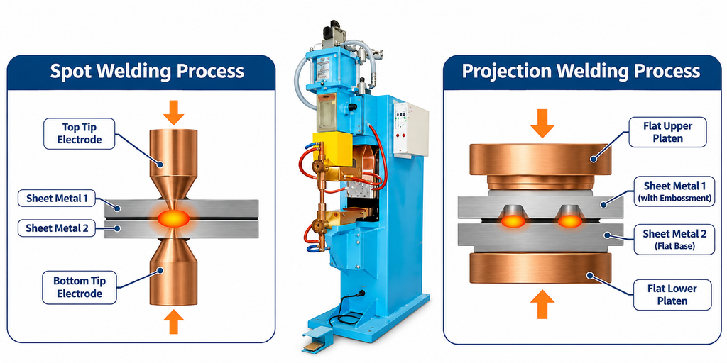
Resistance spot welding concentrates high electrical current and high mechanical force into a localized area using pointed or domed copper alloy electrodes.
Process Dynamics
- Squeeze Phase: Upper and lower copper electrodes clamp the overlapping sheet metal workpieces under preset pneumatic or servo-driven mechanical force.
- Weld Phase: A high-amperage current passes through the electrode tips, melting the faying surface and forming a molten weld nugget.
- Hold Phase: Current cuts off while clamping pressure remains, allowing the molten nugget to solidify rapidly under pressure.
- Off Phase: Electrodes retract for component index or robot movement.
Key Advantages of Spot Welding
- Low Initial Capital Investment: Standard benchtop or pedestal spot welding equipment carries a lower initial machine cost.
- Flexibility in Manual Assembly: Compact spot welding guns can maneuver easily around complex 3D metal fabrications, enclosures, and structural flanges.
- No Material Pre-processing: Requires no pre-stamping or embossing on the metal sheets prior to assembly.
Technical Limitations
- Electrode Tip Mushrooming: Pointed electrodes deform under repetitive heat and mechanical impact, enlarging the contact tip diameter over time. This reduces current density, leading to undersized welds unless tip dressers are regularly deployed.
- Single-Point Productivity: Standard spot setups create only one weld nugget per cycle, limiting throughput on high-density joint configurations.
- Surface Marking: Indentations are left on both outer surfaces where the concentrated electrode tips press into hot metal.
Resistance Projection Welding: Working Principle and Advantages
Projection welding modifies the spot welding concept by shifting current concentration away from the electrode tip and onto pre-formed relief projections (embossments, dimples, or ridges) on one of the workpieces.
Process Dynamics
- Large flat copper platens or custom tooling dies press against the assembly.
- The electrical path compresses directly through the engineered metal projections.
- High current density melts the projections rapidly, causing them to collapse under mechanical force as the base sheets pull flush together.
- Multiple weld points fuse simultaneously across the die area in a single machine stroke.
Key Advantages of Projection Welding
- Multiple Welds per Stroke: Dozens of weld points, weld nuts, or studs can be attached simultaneously in one quick cycle.
- Extended Tooling Lifespan: Large flat platens distribute mechanical loads evenly over wide surface areas, virtually eliminating tip wear and tip dressing maintenance.
- Blemish-Free Aesthetics: Class-A surface finishes can be preserved on the unembossed mating sheet because flat platens leave minimal surface indentation.
- Joining Thick-to-Thin and Dissimilar Metals: Heavy structural brackets, threaded fasteners, and thick plates can be joined securely to thin sheet metal without burning through.
Technical Limitations
- Pre-stamping Requirements: Requires primary stamping operations to form precise embossments or specialized projection weld fasteners.
- Higher Pneumatic/Servo Force Needs: Collapsing multiple solid metal projections simultaneously demands substantially higher forge pressure and machine frame rigidity.
Detailed Technical Comparison: Spot vs. Projection Welding
Understanding how spot and projection welding perform across various manufacturing metrics ensures your shop selects the correct machinery configuration:
| Technical Metric | Resistance Spot Welding | Resistance Projection Welding |
| Current Concentration | Concentrated via tapered copper electrode tips | Concentrated via engineered metal projections/embossments |
| Electrode Wear Rate | High (requires frequent tip dressing/dressing automation) | Very Low (uses large, durable copper platens/dies) |
| Production Speed | 1 weld nugget per machine stroke | Multiple welds / full fastener sets per single stroke |
| Surface Finish Impact | Leaves surface indentations on both sides | Minimal to zero marking on non-projecting Class-A sides |
| Material Thickness Limit | Best for thin gauges (0.5 mm to 3.0 mm) | Excellent for thick plate, studs, weld nuts, and multi-layer stacks |
| Mechanical Rigidity Needs | Moderate machine frame stiffness | Extremely high frame stiffness to prevent platen deflection |
Choosing the Right Machine Architecture for Sheet Metal Assembly
1. Power Supply Architecture: AC vs. MFDC Inverter
Choosing the right power converter drastically impacts weld quality and energy consumption:
- Single-phase AC Spot Welder: Uses traditional transformers operating at standard line frequencies. While cost-effective for basic mild steel fabrications, single-phase AC draws uneven line power, exhibits high thermal losses, and lacks precise energy control over brief millisecond windows.
- Inverter Spot Welding Machine (MFDC): Medium Frequency Direct Current (MFDC) inverters convert incoming 3-phase AC power to 1,000 Hz AC, then rectify it to continuous DC power.
Why MFDC Inverters Outperform Standard AC Units:
- Near-Zero Ripple Energy: Continuous DC power delivers heat uninterrupted into the weld nugget, reducing weld time requirements by 30% to 50%.
- Balanced Electrical Grid Load: 3-phase power drawing eliminates phase imbalances on factory floors.
- Millisecond Control Precision: Advanced controllers regulate current outputs every millisecond, making MFDC essential for high-precision automotive body assembly and non-ferrous metals like aluminum and brass.
2. Force Delivery Systems: Pneumatic vs. Servo Cylinders
Maintaining optimal electrode force throughout the weld cycle is crucial. As projections collapse or metals melt, the force system must follow up rapidly to prevent metal expulsion (sparking):
- Pneumatic Actuators: Low-cost, reliable, and effective for standard sheet metal operations. However, air compressibility can cause minor force delays during rapid projection collapse.
- Servo-Electric Actuators: Provide precise digital control over electrode position, speed, and applied force. Servo units eliminate impact damage to delicate projections during initial touch down, lower noise levels, and ensure fast mechanical follow-up.
Critical Factors When Selecting a Resistance Welder
Material Composition & Metallurgical Properties
- Mild & Carbon Steels: Easy to weld using either spot or projection methods due to moderate electrical resistance and wide thermal processing windows.
- Aluminum Alloys: Feature high thermal and electrical conductivity alongside persistent surface oxide layers. Aluminum requires an inverter spot welding machine with dynamic force follow-up and high peak current capability to form reliable nuggets before heat dissipates.
- Stainless Steels: Possess high electrical resistance and lower thermal conductivity. They require lower weld currents but precise control to prevent carbide precipitation and heat discoloration.
Joint Geometry & Fastener Integration
If your assembly relies on attaching threaded studs, mounting bosses, or heavy brackets to thin enclosures, projection welding is the superior choice. If you are joining long, overlapping sheet metal seams or curved panels, spot welding guns provide unmatched reach and versatility.
Welding Controller & Process Monitoring
A modern digital welding controller monitors welding current, voltage drop across platens, and total energy delivery in real time. Features such as automatic current compensation (ACC), displacement sensors (to measure projection collapse distance), and dynamic weld-logging interfaces guarantee total traceability for critical structural components.
Technical Case Studies: Industrial Applications
Case Study 1: Automotive Body Assembly
In modern automotive body assembly plants, structural strength, weight reduction, and rapid cycle times are paramount.
- The Challenge: Joining multi-layer ultra-high-strength steel (UHSS) pillar structures without causing micro-cracking or weld expulsion.
- The Solution: Deployment of multi-axis robotic arms equipped with 1,000 Hz MFDC inverter spot welding guns.
- The Result: The constant DC current output achieved consistent weld nugget formation within a short current dwell time, preventing heat-affected zone embrittlement while maintaining structural crash safety compliance under AWS D17.2 standards.
Case Study 2: High-Speed Enclosure & Fastener Assembly
An electrical cabinet manufacturer needed to attach eight M8 threaded steel standoffs to 1.5 mm galvanized steel control box panels.
- The Challenge: Manual spot welding of individual studs resulted in thread contamination, uneven alignment, and low production speed (under 40 cabinets per hour).
- The Solution: Migration to a heavy-duty press-type projection resistance welder equipped with customized flat platens and auto-feed stud bowls.
- The Result: All eight studs were projection-welded simultaneously in a single 250-millisecond machine stroke. Production rose to over 240 cabinets per hour with zero thread damage and smooth external surfaces.
Strategic Equipment Engineering Services by Kaiyuan India
Selecting the correct resistance welder requires careful balancing of machine kVA ratings, secondary circuit impedance, mechanical force capabilities, and automation integration. Installing mismatched equipment leads to excessive spatter, poor nugget penetration, and high electrical utility costs.
At Kaiyuan India, we engineer and deliver cutting-edge resistance welding solutions tailored specifically to your manufacturing needs. Whether you require a robust single-phase AC spot welder for general metal fabrication, high-precision press-type projection welders, or advanced MFDC inverter spot welding machine setups for automated lines, our engineering team guides you from initial joint feasibility testing to full turnkey installation.
Our technical team works directly with your engineering staff to:
- Evaluate material weldability and design custom projection geometries.
- Calculate exact kVA and electrode force requirements for your sheet thickness combinations.
- Supply durable, high-conductivity copper alloy tooling dies and automated electrode dressers.
- Integrate intelligent welding controller hardware for real-time quality assurance.
Frequently Asked Questions (FAQs)
What is the main difference between spot welding and projection welding?
Spot welding uses pointed copper alloy tip electrodes to concentrate current directly into a small area on flat sheet metal. Projection welding uses large, flat copper platens to pass current through pre-formed projections (embossments or dimples) on the workpiece, melting those points down simultaneously under high mechanical pressure.
Why is an inverter spot welding machine (MFDC) better than a single-phase AC spot welder?
An inverter spot welding machine operates at higher frequencies (typically 1,000 Hz DC) compared to standard line-frequency AC units. MFDC units draw balanced 3-phase power, consume significantly less energy, provide precise millisecond current control, and deliver constant heat output without thermal drop-offs during zero-crossing AC cycles.
How does electrode force affect weld nugget quality?
Sufficient electrode force squeezes the sheet metal surfaces together to eliminate air gaps, contain the molten weld metal nugget, and prevent spark expulsion. If the force is too low, heavy spatter and surface burning occur. If the force is excessively high, electrical contact resistance drops too far, resulting in undersized or cold weld nuggets.
Can I perform projection welding on a standard spot welding machine?
Not effectively. Projection welding requires significantly higher clamping force to collapse solid metal projections, as well as wide, rigid platens to ensure parallel force distribution. Using small spot welding arms for projection tasks typically leads to frame deflection, uneven projection collapse, and premature machine wear.
How do thermal and electrical conductivity affect material selection for electrodes?
Electrodes must possess much higher thermal and electrical conductivity than the workpieces being welded. High conductivity prevents the electrode from sticking to or overheating the sheet metal surface, ensuring the heat build-up remains concentrated inside the faying interface between the workpieces.
Review structural qualification requirements and resistance welding technician guidelines from the American Welding Society (AWS) Standards.