
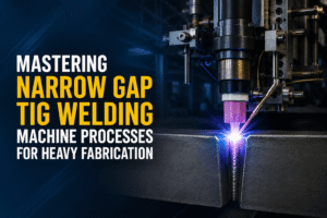
Mastering Narrow Gap TIG Welding Machine Processes for Heavy Fabrication
Modern heavy manufacturing setups constantly face structural and logistical challenges when attempting to efficiently fuse thick metallic sections. Traditional beveling protocols necessitate broad joint configurations that demand massive amounts of consumable filler material and extreme thermal expenditure. Consequently, structural manufacturing facilities run into elevated cycle timelines, structural deformation, and high production operating costs. To circumvent these expensive structural pitfalls, advanced heavy infrastructure engineering teams are shifting away from manual configurations. They are adopting mechanized systems built to deliver high-quality root and filler passes within highly constrained operational tolerances.
Understanding how to orchestrate a high-performance tig welding machine setup within a tight joint profile is essential for achieving deep, flaw-free root fusion in structural steels and high-alloy metals. When dealing with material sections exceeding 50 mm, traditional joint setups fall short under stringent quality inspections. This comprehensive manual explores how Mastering Narrow Gap TIG Welding Machine Processes for Heavy Fabrication can transform your production floor. We will break down operational mechanics, metallurgical considerations, and automation strategies designed to help your workshop operate at peak efficiency.
Section 1: Decoding the Industrial TIG Welder for Narrow Trench Applications
What is TIG Welding Machine Engineering in Specialized Joint Fields?
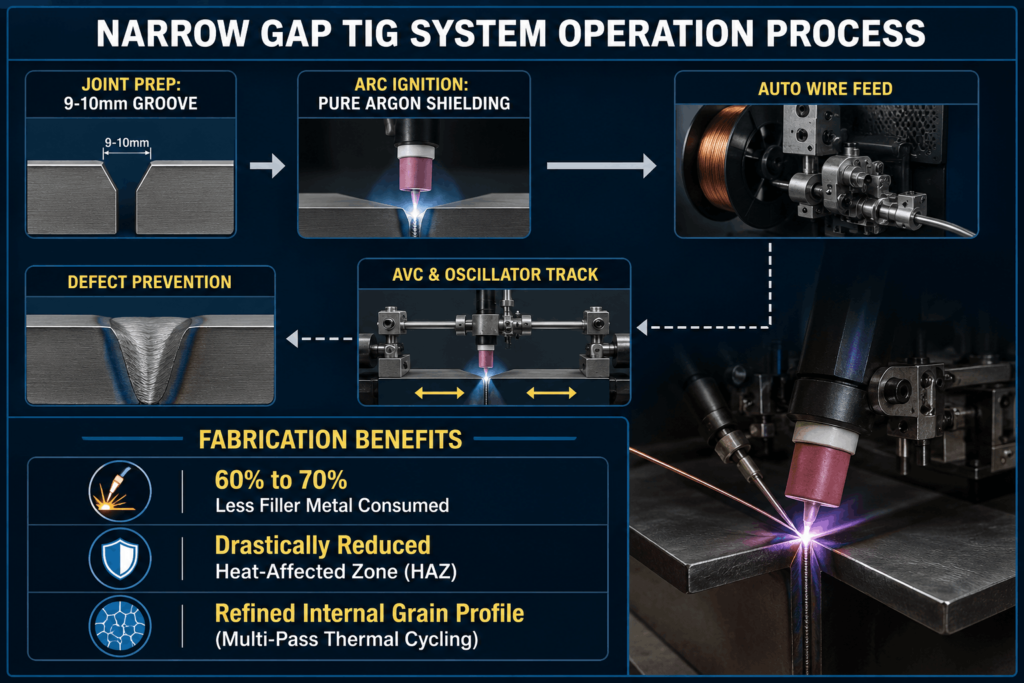
To properly integrate mechanized welding systems into production lines, you must first understand the fundamental engineering of an industrial tig welder. At its core, the Gas Tungsten Arc Welding (GTAW) system establishes a highly stable electrical arc between a non-consumable tungsten electrode and the metal workpiece. In standard setups, this arc is wide open, allowing manual operators sufficient room to manipulate the torch profile. However, inside a narrow groove—where joint sidewalls are separated by an tight width of just 9 to 10 millimeters—a standard manual configuration becomes completely unfeasible.
When analyzing what is tig welding machine technology in modern heavy fabrication, it refers to specialized systems engineered to maintain an incredibly stable arc column deep within a confined metal channel. The process relies on a precision-designed torch nozzle that fits cleanly inside narrow joint sidewalls without short-circuiting. By switching from a standard wide V-groove to an advanced parallel or near-parallel joint configuration, you dramatically reduce the total volume of weld metal needed to fill the joint.
Core Mechanics of the Narrow Gap TIG Welding Subsystem
Operating inside a tight groove requires a specialized narrow gap tig welding torch assembly. Standard torches cannot operate at these depths because the gas cup would hit the top edges of the plates, preventing the arc from reaching the root. Specialized narrow groove systems utilize extended, low-profile water-cooled torches that insert directly into the deep, parallel seam.
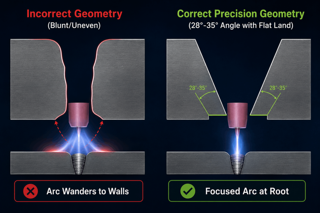
A primary technical obstacle when welding deep inside a 10 mm channel is preventing the electrical arc from wandering or snapping to the adjacent sidewalls. Because electricity follows the path of least resistance, the arc naturally tends to jump to the closest vertical sidewall rather than penetrating straight down into the joint root. Advanced systems resolve this physical limitation by implementing mechanized electrode oscillation. By swinging or rotating the arc precisely between the left, middle, and right sidewall positions, the system guarantees complete tie-ins and defect-free root fusion.
Section 2: Technical Breakdown of the Narrow Gap TIG Process
Thermal Advantages of the Mechanized TIG Process
The specialized tig process offers major metallurgical benefits, particularly when handling heavy structural sections that are sensitive to excessive thermal input. Traditional multi-pass processes expose heavy plates to repeated, prolonged thermal cycles, which can expand the heat-affected zone (HAZ) and degrade the base material’s grain boundaries.
Because a narrow groove configuration requires considerably fewer total passes to fill the seam, the overall thermal load on the assembly is significantly lower. This precise, localized heat control reduces residual stress fields and eliminates the structural distortion that typically warps thick metal plates during fabrication. Furthermore, because the automated system deposits thin, uniform weld beads sequentially, the heat from each consecutive pass acts as a localized thermal treatment for the layers underneath. This continuous, controlled reheating refines the internal grain profile, maximizing impact toughness and tensile strength across the entire cross-section of the weld joint.
Key Specifications of High-Performance Systems
Implementing this advanced technology requires rigorous adherence to precise operating envelopes. The table below details the performance parameters of an automated heavy production setup:
| Process Parameter | Industrial Production Value Range |
| Maximum Structural Plate Thickness | 150 mm (Horizontal Position) up to 600 mm (Flat Position) |
| Operational Groove Seam Width | 9 mm to 10 mm |
| Automated Wire Deposition Speed | 35 to 60 grams per minute |
| Linear System Travel Speed | 50 to 300 millimeters per minute |
| Pass Configuration Structure | Single pass per layer |
| Filler Wire Diameter Selection | 1.2 mm |
| Automated Wire Feed Delivery Rate | 0.2 to 6.8 meters per minute |
Section 3: Essential Equipment Components for Industrial Fabrication
1. Advanced Automated Arc Shielding Systems
Maintaining absolute weld puddle purity at deep production levels requires highly reliable gas coverage. Standard gas cups cannot deliver adequate coverage deep within a 150 mm structural joint. To solve this, automated manufacturing systems leverage specialized argon welding machine components featuring customized trailing gas shields. Pure argon gas flows through independent internal channels within the low-profile torch, providing full coverage over the molten puddle. This specialized gas delivery isolates the active weld zone from atmospheric oxygen and nitrogen, preventing the formation of micro-porosity defects deep within the joint structure.
2. High-Precision Mechanical Torch Oscillators
Achieving complete tie-ins along the vertical side walls of a narrow joint requires highly precise torch oscillation. Advanced production systems integrate mechanical or magnetic oscillation modules that move the tungsten tip according to precise timing parameters. The torch is programmed to dwell briefly at the left sidewall, move rapidly across the center, and dwell at the right sidewall. This precise motion distribution ensures uniform heat delivery, completely eliminating lack-of-fusion defects along the vertical edges of the channel.
3. Integrated Dynamic Arc Voltage Control (AVC)
In deep, narrow joints, even minor variations in surface height or distance can disrupt arc stability, causing the tungsten electrode to stick or burn back. To maintain an unvarying arc gap, automated systems utilize high-speed Arc Voltage Control (AVC) systems. The AVC system continuously measures the electrical feedback from the arc column. If it detects a change in voltage, it instantly triggers a motorized slide to adjust the torch height, keeping the arc length perfectly uniform throughout the entire pass.
Section 4: Advanced Consumables and Specialized Tooling
Precision Tungsten Electrode Selection
Executing high-amperage, long-arc-on time configurations within tight grooves demands highly durable non-consumable electrodes. Standard tungsten welding approaches rely heavily on specialized 2% thoriated or 2% ceriated tungsten rods ground to incredibly tight tolerances. The tip geometry must be machined with a precise angle—typically between 28 and 35 degrees—accompanied by a minor flat land at the tip. This specialized tip geometry prevents the arc from wandering wildly and focuses the thermal energy directly into the root of the narrow gap channel.
Automated Cold Wire Delivery Integration
To maintain high deposition rates without compromising arc stability, industrial setups feature fully integrated automatic TIG wire filling units. Rather than relying on manual operators to feed filler metal into the puddle, a synchronized wire-drive motor feeds a continuous 1.2 mm wire spool directly through a guide nozzle mounted behind the tungsten tip. The wire entry angle and entry point must be precisely calibrated. This ensures the filler metal melts cleanly at the leading edge of the puddle without contacting the tungsten electrode, preventing immediate process contamination.
Section 5: Strategic Structural Applications across Heavy Manufacturing Industries
High-Specification Pressure Vessel Fabrication
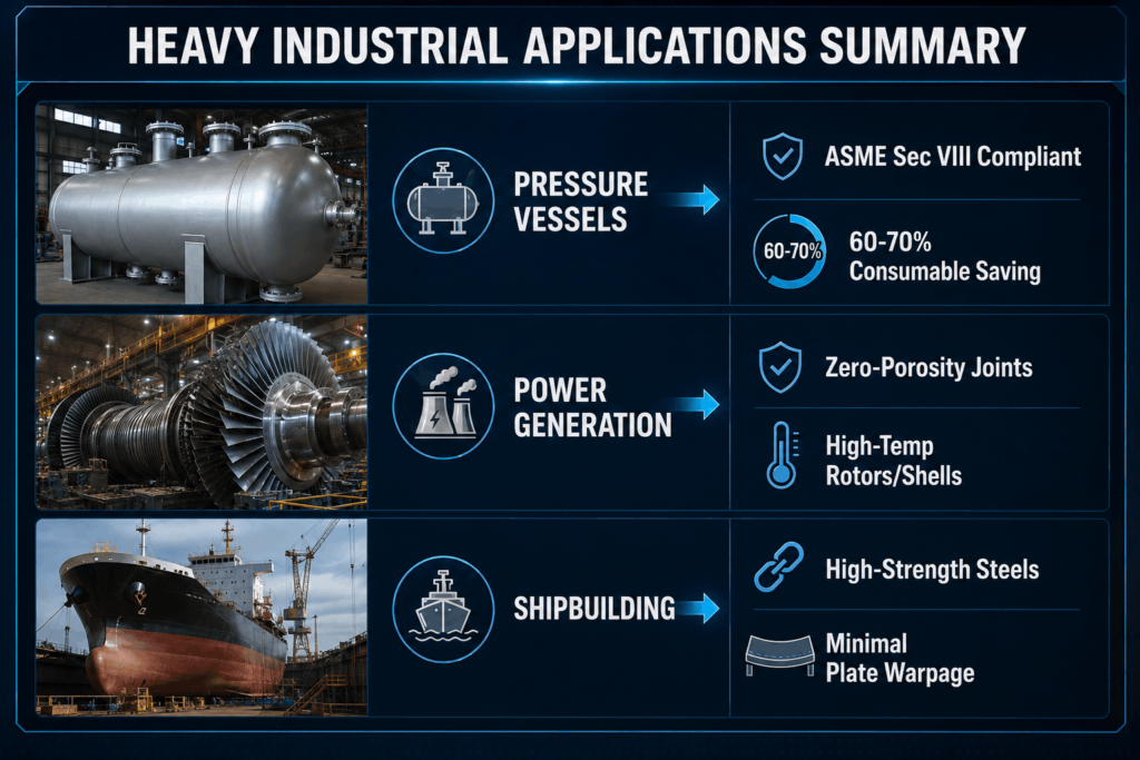
Heavy industrial sectors must adhere to strict regulatory standards, such as the ASME Section VIII design codes for pressurized systems. Within these high-stress applications, implementing pressure vessel welding methods using automated narrow gap systems significantly reduces production turnaround times. Thick-walled storage vessels, boiler components, and heat exchangers feature long circumferential joints that take days to complete using traditional methods. Transitioning to automated parallel-groove setups lets facilities maintain uniform root fusion while reducing total filler metal consumption by 60% to 70%.
Power Generation Infrastructure and Heavy Components
Steam turbine rotors, nuclear reactor containment housings, and high-pressure steam lines require flawless, high-strength welds to operate safely under intense thermal stresses. The mechanized TIG process provides the extreme precision needed to produce zero-porosity joints in these demanding applications. By utilizing specialized automated systems, power generation equipment manufacturers can successfully join exotic creeping steels and nickel-base superalloys while avoiding hot-cracking issues.
Maritime Assembly and Shipbuilding Infrastructure
Modern shipbuilding yards work extensively with thick high-strength low-alloy (HSLA) steel plates to construct submarine hulls and large cargo vessels. Traditional welding methods often introduce high residual stresses that warp structural plates, requiring costly post-weld flame-straightening. Implementing narrow gap automation limits heat input to a narrow band, keeping large panels flat and dimensionally accurate throughout assembly.
Section 6: Preventing Operational Defects in Narrow Gap Profiles
To consistently achieve X-ray-clear welds that pass rigorous non-destructive testing (NDT), production teams must proactively monitor and address specific narrow groove defect conditions:
Sidewall Lack of Fusion
This defect occurs when the electrical arc fails to melt the vertical faces of the joint, leaving a cold lap line along the sidewall. It is usually caused by incorrect torch oscillation parameters or insufficient arc dwell time at the groove edges. To fix this, increase the edge dwell timers on the oscillator control panel or adjust the shielding gas mixture to enhance arc heat transfer.
Entrapped Porosity Formations
Porosity occurs when outside atmospheric gases contaminate the weld puddle before it solidifies. In deep trenches, air pockets can become trapped if the shielding gas flow becomes turbulent. To maintain stable gas coverage, reduce the gas flow rate to avoid turbulence, verify that the trailing shield is properly aligned, and ensure the joint faces are completely free of rust, scale, or cutting oils before starting the pass.
Hot Cracking and Centerline Solidification Segregation
Hot cracking happens when impurities collect along the center line of the weld bead as it cools. This is often caused by an incorrect bead depth-to-width ratio, particularly if a pass is too deep and narrow. To prevent this, adjust the travel speed and wire feed rate to deposit a slightly wider, flatter bead profile that can handle cooling stresses without tearing.
Section 7: Transitioning Workshops from Manual Layouts to Automated Welding
Upgrading a manufacturing facility from manual operations to an automated system requires a well-planned strategy. For a comprehensive look at how automation upgrades boost shop productivity, review this detailed comparison of Automatic Welding Machine vs Manual Welding.
1. High-Precision Joint Preparation Requirements
Narrow gap welding leaves very little room for error; a variation of just 0.5 mm in groove width can disrupt the process. Consequently, standard manual torch cutting or rough plasma gouging is not accurate enough for joint preparation. Heavy fabrication shops must use high-precision edge milling machines or mechanized track cutters to ensure perfectly straight, parallel joint edges across the entire length of the plate.
2. Workforce Training and Skill Upgrades
Transitioning to automation does not mean replacing your skilled operators; instead, it upgrades their responsibilities. Experienced manual welders already understand weld puddle dynamics, making them ideal candidates to become automation technicians. Training programs should focus on teaching operators how to program CNC control interfaces, set up oscillation parameters, and calibrate automated wire feeding assemblies.
3. Integrated Laser Vision Tracking Systems
When welding large, heavy components like pressure vessel shells, minor fit-up variations and tracking errors are bound to occur. To prevent defects, advanced automated systems integrate laser-based vision tracking systems. These sensors scan the joint profile just ahead of the torch, automatically adjusting the machine’s position in real time to compensate for any joint misalignment or fit-up issues.
Section 8: Maximizing Operational ROI with Kaiyuan Automation
Implementing automated narrow gap systems delivers clear financial benefits by driving down production costs and improving shop throughput. For a closer look at the economic advantages of these systems, see this technical guide on How Narrow Gap Welding Reduces Material Cost and Improves Weld Quality.
Drastic Reduction in Filler Metal Consumables
By narrowing the joint angle from a standard 37.5-degree bevel down to a tight 1-to-3-degree parallel groove, shops can slash total filler wire consumption by up to 70%. Minimizing the amount of specialized alloy wire needed keeps projects well within budget and lowers material procurement costs.
Lower Energy Consumption and Arc-On Time
Depositing hundreds of kilograms of filler metal using traditional multi-pass methods requires massive amounts of electrical power over multiple shifts. Because a narrow gap configuration requires significantly less weld volume, total arc-on time is slashed by over 50%. This faster production cycle reduces utility expenses and increases overall shop capacity.
Minimizing Post-Weld Cleanup and Rework
Traditional manual welding processes often leave behind significant spatter and uneven weld beads that require hours of grinding and clean-up. In contrast, automated TIG systems produce smooth, uniform passes with virtually zero spatter. This clean finish minimizes post-weld grinding and helps shops consistently pass non-destructive testing (NDT) on the first try, eliminating costly rework.
Optimize Your Production Line with Kaiyuan’s Automated Systems
Achieving flawless results in heavy fabrication requires a combination of operator expertise and high-precision machinery. Kaiyuan Welding & Cutting Automation India Pvt Ltd designs and manufactures advanced industrial automation systems that help shops tackle tough production challenges with confidence. Our specialized systems provide the precise arc control, steady wire delivery, and reliable tracking needed to optimize your heavy fabrication projects.
Why Partner with Kaiyuan?
- Turnkey Automation Solutions: We offer a full range of advanced systems, including Submerged Arc Welding, Narrow Gap MIG, and specialized Cladding setups tailored to your specific application requirements.
- Proven Field Performance: Built with rugged components and advanced control software, our machines deliver consistent, reliable performance in demanding industrial environments.
- Expert Support Team: Based out of our manufacturing facility in Pune, Maharashtra, our engineering team provides comprehensive technical support, operator training, and system integration services.
Take the guesswork out of heavy component fabrication. Contact our technical engineering team today at info@kaiyuan.in or call us at +91 89566 13642 to discuss your production goals and get a custom system quote. Explore our complete line of advanced automated systems on the official Kaiyuan Product Portfolio.
Technical Q&A: Narrow Gap TIG Systems
Q1: What is the primary difference between a narrow gap TIG system and standard TIG equipment?
Standard TIG equipment relies on manual torch control within wide V-grooves, which requires a large volume of filler metal. Narrow gap systems use specialized, low-profile water-cooled torches that insert deep into narrow 9–10 mm parallel grooves. These automated systems feature precise electrode oscillation and arc voltage tracking to ensure consistent sidewall penetration without short-circuiting.
Q2: Why is pure argon gas preferred for these narrow groove processes?
Pure argon gas provides excellent arc stability and shielding protection within deep, restricted joints. It forms a stable, protective environment that shields the molten puddle from atmospheric contamination, eliminating porosity and ensuring clean, high-quality welds.
Q3: How do automated systems prevent lack-of-fusion defects along vertical sidewalls?
Automated systems utilize advanced mechanical torch oscillators that move the arc precisely across the joint. By programming brief dwell times at each sidewall, the system delivers uniform heat to the edges of the channel, ensuring complete fusion and smooth tie-ins.
Q4: Can narrow gap systems handle different material types like stainless steel or alloy steel?
Yes. These automated systems are highly versatile and excel at joining carbon steel, stainless steel, nickel alloys, and high-strength low-alloy (HSLA) steels. Their precise heat control makes them ideal for working with crack-sensitive materials.
Q5: What plate thicknesses are best suited for narrow gap processes?
While the process can be used on thinner plates, it delivers the best return on investment on heavy sections over 50 mm thick. The system can handle thicknesses up to 150 mm in the horizontal position and up to 600 mm in the flat position, providing major savings in time and material costs.