
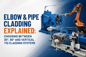
Elbow & Pipe Cladding Explained: Choosing Between 30°, 90° and Vertical TIG Cladding Systems
Industrial piping systems operating in aggressive petrochemical, offshore, and heavy manufacturing environments face constant exposure to severe corrosion, erosion, and high operational pressures. Without adequate protection, critical components like pipe spools and complex fittings experience rapid material degradation, leading to unscheduled shutdowns, massive maintenance costs, and catastrophic safety hazards. This comprehensive guide to Elbow & Pipe Cladding Explained: Choosing Between 30°, 90° and Vertical TIG Cladding Systems breaks down how modern weld overlay cladding techniques safeguard high-value assets and extend operational longevity.
Weld overlay cladding deposits a high-performance, corrosion-resistant alloy (CRA)—such as Inconel 625, Hastelloy, or 300-series Stainless Steel—onto a lower-cost carbon steel substrate. Consequently, industrial engineers gain the mechanical strength of structural steel combined with the chemical immunity of nickel-based alloys at a fraction of the cost of solid CRA piping.
However, applying an even, defect-free CRA layer inside curved geometries and straight pipe bores presents unique mechanical challenges. Selecting the correct automation configuration—whether a 30° TIG cladding system, a 90° elbow cladding rig, or a high-capacity vertical TIG cladding system—determines your weld quality, dilution control, and overall operational efficiency.
What is Pipe Cladding and Weld Overlay Integration?
Pipe cladding is an advanced metallurgical process where a corrosion-resistant or hardfacing alloy fuses continuously onto the inner or outer surface of a metallic component. Unlike mechanical lining, which relies on friction fits or hydraulic expansion, weld overlay cladding creates a true atomic bond. As a result, the cladding layer will not delaminate, buckle, or separate under extreme thermal cycling, pressure fluctuations, or intense mechanical stress.
Modern manufacturing facilities utilize automated tungsten inert gas cladding machine setups to maintain tight tolerances and repeatable bead profiles. Gas Tungsten Arc Welding (GTAW/TIG), specifically Hot Wire TIG cladding, remains the gold standard for critical CRA application.
Why GTAW/TIG Leads the Cladding Industry
- Superior Dilution Control: Hot Wire TIG allows independent control over heat input and wire feed rates. Consequently, it minimizes the mixing of carbon steel base metal into the CRA deposit, keeping iron dilution below the strict 5% industry standard in a single or double pass.
- Flawless Arc Stability: The non-consumable tungsten electrode generates a clean, precise arc that produces zero spatter, significantly reducing post-weld cleanup.
- Volumetric Integrity: TIG cladding produces non-porous deposits that pass 100% ultrasonic testing (UT) and dye penetrant testing (PT) inspection criteria mandated by international standards like API Spec 6A and ASME Section IX.
The Role of Automated Pipe Cladding Equipment in Modern Manufacturing
Manual weld overlay on inner pipe diameters (ID) is labor-intensive, hazardous, and prone to human error. Variations in torch angle, arc length, and travel speed cause inconsistent deposit thickness, high iron dilution, and fusion defects.
Advanced automated pipe cladding equipment eliminates these variables. These specialized automated rigs integrate heavy-duty mechanical positioners, multi-axis torch manipulators, closed-circuit industrial camera systems, and programmable PLC controllers.
When dynamic arc length control (AVC) combines with continuous wire feeding, automated cladding machinery delivers precise bead overlap, even inside tight-tolerance bores and complex elbows. By removing human error from the equation, automated systems yield high deposition rates while maintaining low heat input.
Deciphering Cladding Geometries: Elbows vs. Straight Pipes
To select the right machinery, engineers must evaluate the geometric differences between straight pipe spools and curved elbows.
Straight pipes feature a uniform central axis, allowing a welding lance to travel linearly down the bore while the pipe rotates on turning rolls. In contrast, pipe elbows present a complex 3D contour:
- The Extrados (Outer Radius): Requires a longer surface travel path and higher wire deposition to maintain uniform wall thickness.
- The Intrados (Inner Radius): Requires a shorter travel path with reduced heat input to prevent molten pool sagging and excessive buildup.
Because the arc torch must maintain a perpendicular angle to the changing contour, standard straight-bore cladding lances cannot operate inside elbows without specialized articulating joints or angled torch heads.
System Analysis: 30° TIG Cladding Systems
The 30° TIG cladding system is an engineered solution tailored specifically for shallow-angle elbows, custom bends, and transitional pipe fittings where standard vertical or 90° systems encounter physical clearance limits.
Key Technical Characteristics
- Articulated Lance Mechanics: The welding head features a compact 30° offset block, enabling torch manipulation around subtle internal radii.
- Optimized Pool Control: Angling the torch at 30° allows gravity to stabilize the molten weld pool when traversing shallow internal curves.
- Compact ID Reach: Designed to enter smaller internal diameters (down to 2 inches / 50 mm) where right-angle drive heads are too bulky.
Ideal Applications
30° systems excel in clad overlay operations on custom oil and gas manifolds, 30° pipe bends, forged valve bodies, and reducers where spatial constraints prevent direct 90° perpendicular access.
System Analysis: 90° Elbow Cladding Rigs
When manufacturing standard long-radius or short-radius 90° pipe elbows, a specialized 90° elbow cladding rig provides the mechanical precision required to sweep through sharp turns.
Mechanism of Action
A 90° cladding system coordinates rotary positioning with dual-axis torch articulation. As the elbow rotates along its central radius, the internal lance tilts dynamically to keep the tungsten electrode perpendicular to the intrados, extrados, and side walls throughout the entire 90-degree sweep.
Advantages of Dedicated 90° Rigs
- Balanced Heat Input: Advanced controllers dynamically adjust travel speed as the torch transitions from the extrados to the intrados, maintaining an even clad thickness.
- Multi-Pass Capability: Designed to perform uninterrupted root and cap passes with precise indexing between overlapping weld beads.
- High Production Yield: Dedicated 90° rigs streamline component loading, drastically reducing cycle times for valve fittings and standard elbow production lines.
System Analysis: Vertical TIG Cladding Systems
For long, straight pipe spools, heavy-wall cylinders, and high-volume clad production, the vertical TIG cladding system offers maximum stability and efficiency.
Why Vertical Alignment Outperforms Horizontal Methods
When cladding long internal bores horizontally, gravity pulls the molten weld pool downward. This asymmetric pull causes bead sagging, uneven cladding thickness, and arc instability along the upper ceiling of the pipe bore.
Vertical TIG systems solve this by mounting the pipe spool upright on a motorized rotary chuck while a rigid vertical column drives the cladding lance top-to-bottom or bottom-to-top.
Performance Benefits of Vertical TIG Cladding
- Uniform Gravitational Force: Because the weld pool rotates around a vertical axis, gravity acts uniformly across the entire bead width, eliminating sagging.
- Extensive Length Capacity: Vertical rigs can clad straight pipe sections exceeding 6 meters (20 feet) in length without lance deflection.
- Higher Deposition Rates: Enhanced pool stability allows operators to use higher wire feed speeds and hot-wire current, maximizing hourly metal deposition.
Comparative Matrix: Selecting the Right Cladding System
Choosing the correct machine configuration requires balancing component geometry, operational space, and production volume.
| Feature / Metric | 30° TIG Cladding System | 90° Elbow Cladding Rig | Vertical TIG Cladding System |
| Primary Geometry | Shallow bends, reducers, forgings | Standard 90° & 45° elbows | Straight pipes, long cylinders |
| Bore Size Range | Compact ID (2″ to 12″) | Medium to Large ID (3″ to 36″) | Large Range (3″ to 60″+) |
| Torch Motion | Fixed angle, multi-axis shift | Curved sweeping trajectory | Linear vertical travel |
| Deposition Rate | Moderate | Moderate to High | High (Hot-Wire TIG) |
| Gravity Control | Moderate (Requires tuning) | Complex (Dynamic offset) | Optimal (Symmetrical) |
| Setup Complexity | High (Custom alignment) | High (Radius programming) | Low to Medium |
Corrosion-Resistant Alloys (CRA) Used in Cladding
The performance of any clad component relies on matching the appropriate alloy overlay to the specific corrosive media:
- Inconel 625 (UNS N06625): The industry standard for oilfield and subsea applications. It provides exceptional resistance to pitting, crevice corrosion, and chloride-induced stress corrosion cracking.
- Hastelloy C-22 / C-276: Preferred for chemical processing units exposing components to strong oxidizers, wet chlorine, and ferric acids.
- 300-Series Stainless Steel (e.g., 300-Series Stainless Steel / 316L): Offers cost-effective protection against general atmospheric and aqueous corrosion in power generation and refining.
Selecting an optimized cladding machine ensures these expensive alloys deposit smoothly with minimal iron dilution, keeping performance high and material costs low.
Quality Assurance, NDT, and Industry Compliance
Clad pipe spools and fittings must pass rigorous quality control metrics before deployment in high-pressure, high-temperature (HPHT) environments.
Critical Quality Checks
- Chemical Composition Analysis: Positive Material Identification (PMI) and energy-dispersive X-ray spectroscopy verify that the top layer maintains the required alloy composition (e.g., Fe < 5% for Inconel 625).
- Nondestructive Testing (NDT): Liquid Penetrant Testing (PT) checks for surface cracks, while Ultrasonic Testing (UT) inspects bond integrity and measures clad thickness.
- Hardness Testing: Micro-hardness traverses confirm that heat-affected zones (HAZ) in the carbon steel base metal stay within NACE MR0175/ISO 15156 limit values to prevent sulfide stress cracking.
Key Maintenance Strategies for Cladding Machinery
Maintaining mechanical precision in automated cladding equipment requires proactive care:
- Tungsten & Torch Care: Inspect GTAW torches daily for gas lens degradation and maintain consistent tungsten tip geometry.
- Calibration of Axis Motors: Recalibrate servo drives and AVC sensors regularly to ensure smooth trajectory movement inside elbows.
- Wire Feed System Upkeep: Clean wire feed rollers and liner conduits to prevent wire slipping, which causes arc interruptions and burn-backs.
Transform Your Weld Overlay Capabilities with Kaiyuan Solutions
Precision engineering demands reliable, high-performance automation. As an industry-leading manufacturer of automated welding, cutting, and cladding systems, Kaiyuan delivers state-of-the-art technological solutions that empower fabricators worldwide.
Whether your production facility requires a high-throughput vertical TIG cladding system for long pipe spools or a multi-axis 90° elbow cladding rig for complex fittings, Kaiyuan designs robust equipment built to exceed international quality standards.
Explore our complete line of advanced manufacturing machinery:
- Discover our specialized automated cladding machine systems built for demanding energy sectors.
- Upgrade your heavy structural fabrication with high-efficiency submerged arc welding machines.
- Streamline component manipulation using engineered welding positioners and turning rolls.
Partner with Kaiyuan to elevate your cladding productivity, eliminate costly weld defects, and maximize your operational throughput. Contact our technical team today to discuss your project requirements.
Frequently Asked Questions (Q&A)
Q1: What is the main difference between cladding and mechanical lining?
Weld overlay cladding creates a permanent, atomic bond between the CRA and the base metal using fusion welding. Mechanical lining simply expands a thin CRA pipe inside a carbon steel pipe without thermal fusion. Consequently, clad pipes can withstand high pressures, extreme temperatures, and vacuum conditions without risk of liner collapse or separation.
Q2: Why is iron dilution critical during TIG cladding with Inconel 625?
Iron dilution occurs when the carbon steel base metal melts and mixes into the deposited alloy layer. If the iron content in the outer cladding exceeds 5%, the corrosion resistance of Inconel 625 degrades significantly, making the component vulnerable to pitting and stress corrosion cracking.
Q3: How do dynamic Arc Voltage Control (AVC) systems work in elbow cladding?
AVC systems monitor electrical voltage across the welding arc in real time. If the distance between the tungsten tip and the curving elbow wall changes, the AVC adjusts the torch position instantly. This maintains a constant arc length, stable heat input, and uniform weld bead profile throughout the sweep.
Q4: When should I choose a vertical TIG cladding system over a horizontal system?
You should select a vertical TIG cladding system when processing straight pipe spools longer than 1 to 2 meters, or when working with larger bore diameters. The vertical orientation uses gravity to keep the molten weld pool symmetrical, preventing sagging and allowing higher wire deposition rates.
Q5: Can a 90° elbow cladding machine process 45° elbows as well?
Yes. Most advanced 90° elbow cladding rigs feature programmable PLC controllers that allow operators to adjust the sweep angle. As a result, the same system can clad 45°, 60°, and 90° elbow configurations efficiently.